Quick Answer: In a modern off-grid solar power system architecture, Off-grid high-voltage MPPT systems (120–500V DC) allow longer series PV strings instead of complex parallel arrays. Since P = V × I, stepping up string voltage proportionally drops the operating current. Joule’s Law (Ploss = I²R) dictates the rest. Halving the current slashes heat loss by 75%. EPCs and installers can then swap heavy 95mm² copper for standard 4mm² solar cable. This cuts copper usage, minimizes voltage drop on long runs, and streamlines BOS installation.
| Parameter | Low-Voltage String MPPT (≤100V DC) | High-Voltage String MPPT (120–500V DC Operating Range) | Engineering Benefit |
| Circuit Topology | Multi-string parallel | Extended series strings | Eliminates combiner boxes and parallel wiring runs |
| Transmission Current | High (50–100A) | Low (10–27A) | Cuts thermal stress on conductors and terminals |
| Required DC Cable Size | 25mm² to 95mm² copper | 4mm² to 6mm² PV wire | Slashes copper weight and cable BOM costs |
| Line Power Losses (I²R) | High thermal dissipation | Low I²R losses at reduced amperage | Maximizes array-to-inverter yield |
| Max Distance to Inverter | Severely restricted by high-current voltage drop | Supports long homeruns within standard 2–3% drop limits | Simplifies ground-mount and rooftop array placement |
1. Electrical Fundamentals: Voltage vs. Current Dynamics in PV Arrays
In an off-grid solar power system, DC circuit design centers on one core challenge: minimizing I²R resistive heat loss between the PV array and the hybrid inverter. Keeping this thermal dissipation low while maintaining practical conductor cross-sections depends directly on the array’s operating voltage.
1.1 The Relationship Between String Voltage, Amperage, and Power Output (P = V × I)
Electrical power (P) transferred through a circuit is the product of voltage (V) and current (I):
P = V × I
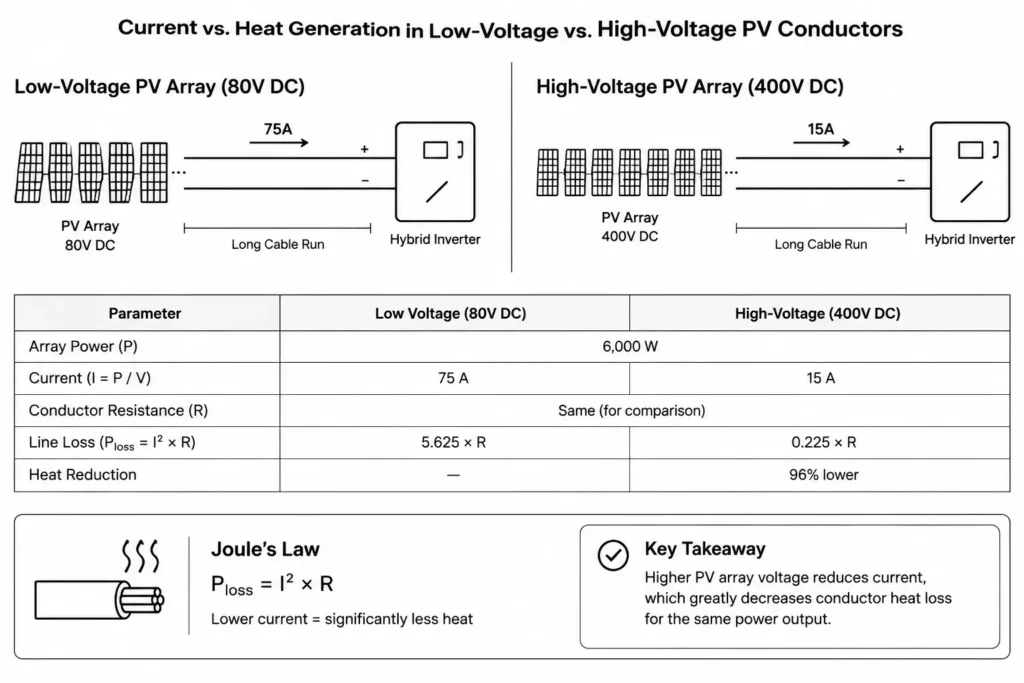
For a fixed 6,000W array, current scales inversely with string voltage:
I = P / V
At a low string voltage of 80V DC, conductors must carry 75A:
I = 6,000W / 80V = 75A
Stepping the array up to a 400V DC series string slashes operating current to 15A:
I = 6,000W / 400V = 15A
Stepping up voltage fivefold cuts transmission current by 80%.
1.2 Joule’s Law (Ploss = I²R) and Thermal Loss Kinetics
Conductor power dissipation follows Joule’s Law:
Ploss = I² × R
Where:
- Ploss = Power lost as heat in the cable (Watts)
- I = Conductor current (Amps)
- R = Total electrical resistance of the copper wire loop (Ohms)
Because current is squared, thermal losses scale exponentially. Small amperage increases generate massive conductor heating.
Halving current cuts conductor losses to 25%.
Dropping current from 75A to 15A slashes line losses by a factor of 25—a 96% reduction in heat dissipation.
Higher string voltages preserve array yield over long homerun distances while staying safely within inverter MPPT windows.
2. Mathematical Proof: Cable Cross-Section Area & Voltage Drop Calculations
Field standards dictate limiting DC voltage drop to 1–3% of nominal string voltage under peak generation. Excessive drop dissipates energy as heat and triggers MPPT hunting.
2.1 Standard Conductor Sizing Formula for DC Circuits
Use standard loop parameters to calculate the required conductor cross-section for solar DC cable sizing:
A = (2 × L × I × ρ) / ΔV
Where:
- A = Required conductor cross-sectional area (mm²)
- L = One-way route distance from the PV array to the inverter or MPPT input (meters)
- I = Peak DC current transmitted (Amps)
- ρ = Copper resistivity (0.0175 Ω·mm²/m at 20°C reference temperature)
- ΔV = Maximum allowable voltage drop across the circuit (Volts)
The multiplier 2 accounts for total loop distance across positive and negative runs in arrays like 610w solar panels.
2.2 Voltage Drop Limits Under IEC 60364-7-712 Guidelines
IEC 60364-7-712 mandates strict voltage drop thresholds between array and inverter to protect peak yield.
Low-voltage strings severely restrict allowable voltage drop (ΔV). A 2% limit at 80V DC leaves a razor-thin 1.6V window; at 400V DC, that margin expands to 8.0V.
Coupling higher voltages with lower currents slashes copper sizing. Pairing this with optimized architectures—like Single MPPT vs Dual MPPT configurations in off-grid solar kits—maximizes BOS efficiency.
Verify conductor cross-sections against IEC 60228 conductor resistance standards to maintain DC loop drop within calculated margins:
| Conductor Size (mm²) | Resistance at 20°C (Ω/km) | Typical Continuous DC Current Reference (A) |
| 2.5 | 7.41 | 20 |
| 4.0 | 4.61 | 30 |
| 6.0 | 3.08 | 40 |
| 10.0 | 1.83 | 55 |
| 16.0 | 1.15 | 75 |
| 25.0 | 0.727 | 100 |
| 50.0 | 0.387 | 150 |
| 95.0 | 0.193 | 230 |
3. Field Sizing Example: 6kW Solar Array (Low-Voltage vs. High-Voltage MPPT)
Consider a typical field installation: a 6kW ground-mount array sited 50 meters from the powerhouse (100-meter DC round-trip loop).
The array consists of 10 units of Haven Deer 610W Grade A Monocrystalline PV Modules with the following Standard Test Condition (STC) ratings:
- Rated Power (Pmax): 610W
- Maximum Power Voltage (Vmp): 40.8V DC
- Maximum Power Current (Imp): 14.95A
- Open Circuit Voltage (Voc): 49.0V DC
3.1 Case A: Parallel/Low-Voltage Configuration (100V DC Max Input)
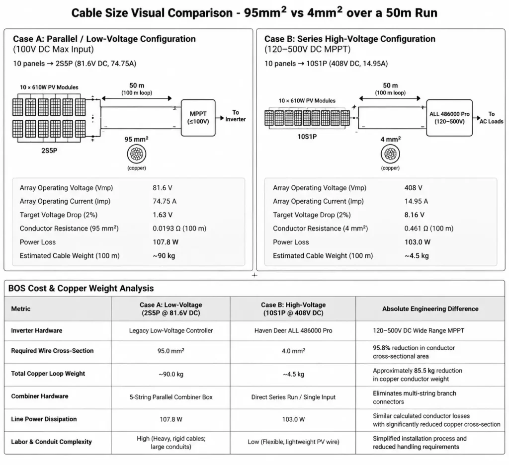
A legacy 100V MPPT controller cannot accept a single series string; 10 panels produce 490V Voc at STC, far exceeding the input ceiling. The installer must parallel the array into a 2-series, 5-parallel (2S5P) configuration.
- Array Operating Voltage (Vmp): 2 × 40.8V = 81.6V DC
- Array Operating Current (Imp): 5 × 14.95A = 74.75A
- Target Voltage Drop Limit (2% of 81.6V): ΔV = 1.63V
Using the conductor area formula:
A = (2 × 50m × 74.75A × 0.0175 Ω·mm²/m) / 1.63V = 80.25 mm²
Meeting the 2% drop target forces an upgrade to 95mm² copper.
- Conductor Resistance (95mm²): 0.193 Ω/km = 0.0193 Ω for 100m loop
- Actual Power Loss: Ploss = (74.75A)² × 0.0193 Ω = 107.8 Watts
- Estimated Cable Weight (100m copper): ~90 kg
3.2 Case B: Series High-Voltage Configuration (120–500V DC MPPT)
Running the same array into a Haven Deer ALL 486000 Pro hybrid solar inverter leverages a 120–500V DC MPPT operating window.
Its 500V DC ceiling allows a single 10-panel series string (10S1P), assuming cold-weather Voc stays within margin.
- Array Operating Voltage (Vmp): 10 × 40.8V = 408V DC
- Array Operating Current (Imp): 1 × 14.95A = 14.95A
- Target Voltage Drop Limit (2% of 408V): ΔV = 8.16V
Using the conductor area formula:
A = (2 × 50m × 14.95A × 0.0175 Ω·mm²/m) / 8.16V = 3.21 mm²
Standard 4mm² PV wire easily handles the load.
- Conductor Resistance (4mm²): 4.61 Ω/km = 0.461 Ω for 100m loop
- Actual Power Loss: Ploss = (14.95A)² × 0.461 Ω = 103.0 Watts
- Estimated Cable Weight (100m copper): ~4.5 kg
3.3 Balance-of-System (BOS) Cost & Copper Weight Analysis
| Metric | Case A: Low-Voltage (2S5P @ 81.6V DC) | Case B: High-Voltage (10S1P @ 408V DC) | Absolute Engineering Difference |
| Inverter Hardware | Legacy Low-Voltage Controller | Haven Deer ALL 486000 Pro | 120–500V DC Wide Range MPPT |
| Required Wire Cross-Section | 95.0 mm² | 4.0 mm² | 95.8% cross-section reduction |
| Total Copper Loop Weight | ~90.0 kg | ~4.5 kg | 85.5 kg copper saved (95% reduction) |
| Combiner Hardware | 5-String Parallel Combiner Box | Direct Series Run / Single Input | Eliminates combiner box & branch connectors |
| Line Power Dissipation | 107.8 W | 103.0 W | Parity line losses at a fraction of the copper volume |
| Labor & Conduit Complexity | High (Rigid 95mm² cable; heavy conduits) | Low (Flexible 4mm² PV wire) | Fast pull times through standard 3/4″ conduit; no heavy wire benders needed |
4. Engineering Design Rules for 120–500V DC MPPT String Sizing
Wide-range MPPT tracking offers design flexibility, but cold weather can quickly push string voltage past hardware limits.
4.1 Calculating Cold-Weather Open-Circuit Voltage (Voc) Safety Margins
PV modules exhibit a negative voltage temperature coefficient, so open-circuit voltage (Voc) rises as temperature drops. A cold weather Voc calculation is essential: an array rated at 440V under STC can easily exceed 500V on a sub-zero morning and damage the inverter’s DC front-end.
Size your series strings to stay safely below the inverter’s 500V DC input limit by applying the standard cold-temperature correction:
Voc,max = Voc,STC × [1 + (γVoc / 100) × (Tmin – 25)]
Where:
- Voc,max = Maximum string open-circuit voltage at lowest anticipated temperature
- Voc,STC = Baseline string open-circuit voltage at 25°C STC (Module quantity × module Voc)
- γVoc = Temperature coefficient of Voc (%/°C, negative value, e.g., -0.28%/°C)
- Tmin = Lowest expected site ambient temperature (°C)
Worked Cold-Weather Example:
A string of 9 Haven Deer 610W panels (Voc = 49.0V at STC) has a baseline voltage of 441V DC at 25°C. For an installation seeing winter lows of -15°C and panel γVoc of -0.28%/°C:
- Temperature Difference: Tmin – 25 = -15 – 25 = -40°C
- Voltage Multiplier: 1 + [(-0.28 / 100) × -40] = 1 + 0.112 = 1.112 (+11.2% voltage rise)
- Maximum Cold String Voltage: Voc,max = 441V × 1.112 = 490.4V DC
At 490.4V DC, a 9-panel string safely clears the 500V input ceiling. This leaves a 9.6V safety margin on the coldest mornings.
4.2 Staying Within Optimal MPPT Efficiency Bands (300–400V DC)
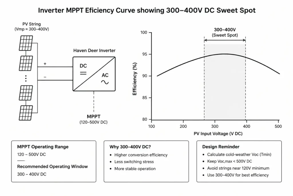
While the Haven Deer ALL 486000 Pro tracks down to 120V DC, the power stage hits peak conversion efficiency between 300V DC and 400V DC. Centering nominal Vmp here minimizes internal switching stress and thermal dissipation.
For dual-tracker units like the Haven Deer ALL 4812000 Pro (12kW Dual MPPT, 60–500V DC), split large arrays into two balanced series strings to maximize independent tracker yields.
Field Rule of Thumb: Avoid bottoming out the MPPT range. Running a string near the 120V minimum (e.g., three 40V modules) forces the boost stage to draw high internal currents, hurting efficiency. Always target a nominal 300–400V Vmp sweet spot.
5. System Integration & DC Circuit Protection Requirements
High-voltage DC demands zero tolerance for cutting corners on isolation and circuit protection. Unlike AC, DC has no natural zero-crossing. Breaking high-voltage DC creates sustained, destructive arcs. Every switch, breaker, and fuse in the array homerun must feature dedicated magnetic arc blowouts and rated DC creepage distances.
5.1 Selecting Fuses, Breakers, and SPDs for 500V DC Circuits
- DC Circuit Breakers: Use non-polarized, DC-rated switchgear rated for 500V+ with integrated arc chutes. Never substitute AC breakers—without a zero-crossing, contacts will weld shut under load.
- String Fuses: Install IEC 60269-6 certified gPV fuses rated for 1,000V DC and sized to 1.25–1.56× Isc on paralleled arrays to clear reverse-current faults.
- Surge Protective Devices (SPDs): Land Type 2 DC SPDs tested to IEC 61643-31 (Up ≤ 2.0 kV, 600V DC operating ceiling) on both poles to clamp indirect lightning strikes and inductive switching transients.
5.2 Streamlining Wiring with IP65 PV Combiner Boxes
Factory-engineered IP65 PV Combiner Boxes eliminate messy, field-wired enclosures and guarantee rapid IEC 60364-7-712 compliance.
The enclosure pre-wires finger-safe gPV fuse holders, a 2-pole 63A DC isolator, and a Type 2 SPD inside a weather-sealed housing. Mounting this combiner adjacent to the array provides an immediate single-point DC disconnect before running 4mm² or 6mm² PV homeruns back to the hybrid inverter.
IEC 60364-7-712 Compliance Checklist for High-Voltage MPPT Installations:
- Voltage Limits: Maximum cold-weather Voc (Voc,max) verified below the inverter’s 500V DC hard limit.
- Protection Hardware: DC-rated isolators and Type 2 SPDs installed ahead of the inverter PV terminals.
- Conductor Marking: DC runs permanently flagged with clear polarity (+ / -) and high-voltage warnings (>120V DC).
- Conductor Sizing: Cross-section verified to hold DC round-trip voltage drop below 2% at peak output.
- Enclosure Rating: Outdoor switchgear sealed inside UV-stabilized, IP65-rated enclosures.
- Earthing & Grounding: Module racks and combiner ground lugs bonded back to the central site electrode system.
6. Frequently Asked Questions (FAQ)
Why does high MPPT voltage allow thinner solar wires?
Power equals voltage times current (P = V × I). Stepping up string voltage slashes amperage for the same wattage. Because cable sizing depends directly on current, lower amperage allows an installer to drop conductor size from 95mm² down to standard 4mm² or 6mm² wire without exceeding a 2% drop limit.
What is the maximum PV open-circuit voltage for Haven Deer hybrid inverters?
Both the Haven Deer ALL 486000 Pro (6kW) and ALL 4812000 Pro (12kW) feature a hard 500V DC maximum input ceiling (Voc,max).
What is the optimal operating MPPT voltage range for a 6kW off-grid inverter?
Target 300V to 400V DC nominal Vmp. Although the inverter tracks down to 120V DC, running between 300V and 400V hits the power stage’s sweet spot for peak conversion efficiency and lowest thermal stress.
How do low winter temperatures affect MPPT string design?
Freezing temperatures spike panel Voc. Silicon has a negative temperature coefficient (typically -0.26% to -0.30%/°C). Always calculate worst-case winter voltage (Voc,max) against local record lows so cold morning spikes never exceed the 500V DC hard limit.
Can I run a 500V DC MPPT PV array directly to a 48V battery bank?
Yes. The inverter’s internal high-voltage MPPT buck stage steps 120–500V DC string power down to charge nominal 48V (51.2V) LiFePO4 banks at high conversion efficiency.
How does high-voltage MPPT impact voltage drop over long distances?
Voltage drop scales directly with current (ΔV = I × R). Slashing current from 75A to 15A drops line loss by 96%, letting you run DC homeruns 50–100+ meters without exceeding a 2% drop or buying expensive, heavy copper.
Is a PV combiner box required for high-voltage MPPT inverters?
Not mandatory for a single string, but strongly recommended. A dedicated IP65 PV Combiner Box places local isolation, 1,000V DC gPV fuses, and Type 2 surge protection directly at the array, ensuring fast IEC 60364-7-712 compliance.
What wire gauge is recommended for a 500V DC MPPT PV string?
Standard 4mm² (12 AWG) or 6mm² (10 AWG) XLPO solar wire. At typical string currents of 10–18A, 4mm² handles one-way runs up to 50 meters within a 2% drop limit. Move up to 6mm² for homeruns beyond 60 meters.
How many 610W panels can be connected in series to a 500V DC MPPT?
Usually 8 to 9 panels per string. At 49.0V STC, 9 panels sit at 441V at 25°C. At -15°C, temperature-corrected Voc rises to ~490V DC, leaving a safe ~10V margin below the 500V ceiling. For regions dipping to -25°C or lower, drop to 8 panels.
Does high voltage increase arcing risks, and how is it mitigated?
Yes. High-voltage DC sustains intense, non-extinguishing arcs across loose terminals. Mitigate this by never cross-mating different MC4 brands, torquing screw terminals to exact manufacturer specs, using switchgear with dedicated arc chutes, and enabling AFCI protection.
7. Optimized Off-Grid System Architecture
Dialing in cold-weather Voc limits or sizing long-distance DC homeruns requires zero margin for error. Our application engineers can audit your string design and verify conductor ampacity before installation.
Send over your site specs to receive a Single-Line Diagram (SLD) review, voltage drop calculations, and a factory-matched off-grid solar power system bill of materials (BOM).