📌Quick Answer: Modern off-grid solar Energy Storage System (ESS) kit architecture is an integrated multi-source energy framework that uses a central Energy Hub (Hybrid Inverter with built-in EMS) to coordinate Photovoltaics (PV), LiFePO4 battery storage, utility grid input, and auxiliary AC generators. Governed by a two-tiered control layer—a Battery Management System (BMS) for cell safety and an Energy Management System (EMS) for system-level energy dispatch—it manages multi-source DC and AC power flows to deliver continuous electricity with UPS-level transfer speeds ( ≤10ms) without grid dependency.
Table of Contents
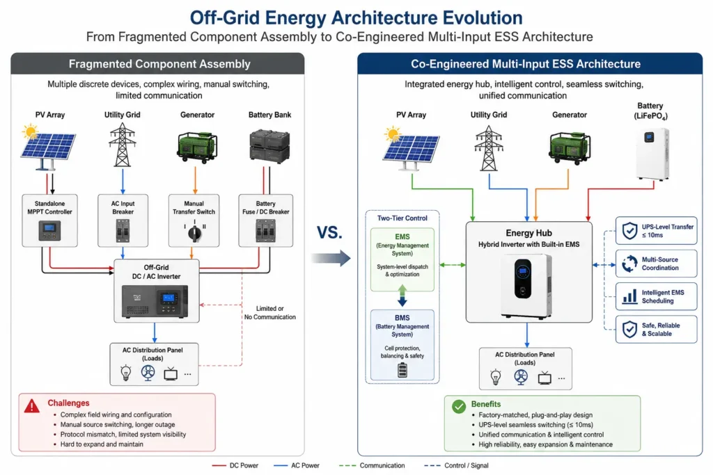
Off-grid energy architecture has undergone a fundamental transition over the past decade. Historical stand-alone systems relied on piecemeal component selection—combining standalone charge controllers, off-grid DC-to-AC inverters, lead-acid battery banks, and manual transfer switches from disparate manufacturers. These legacy setups required complex manual field wiring, suffered from protocol misalignments, and lacked unified energy control logic.
Modern off-grid solar Energy Storage System (ESS) kits address these challenges through factory-matched, multi-input energy hub topologies. By combining high-voltage Maximum Power Point Tracking (MPPT) solar regulation, bidirectional battery inversion, intelligent multi-source scheduling, and layered system communications into a unified system, integrated ESS kits provide continuous, autonomous power for residential, agricultural, and commercial sites.
1.From Component Assembly to Integrated Architecture: The Off-Grid Paradigm Shift
In high-reliability off-grid applications, the engineering design paradigm has shifted from isolated hardware selection to holistic system integration. Understanding the physical and operational limitations of traditional component assembly highlights the benefits of factory-matched solar ESS kits.
1.1 The Limitations of Hardware Sourcing from Fragmented Vendors
Sourcing off-grid hardware from multiple independent manufacturers creates inherent system integration challenges:
Protocol Mismatches and Open-Loop Blindness: When a battery bank’s BMS cannot communicate natively with the solar inverter, the system falls back to open-loop voltage-based control. Because terminal voltage under heavy load or high charge currents does not correlate linearly with Lithium Iron Phosphate (LiFePO4) State of Charge (SOC), voltage-based control often leads to unexpected low-voltage cutoffs, inaccurate capacity readings, and reduced battery service life.
Uncoordinated Protection Curves: Isolated components operate with uncoordinated internal protection boundaries. For example, if an inverter’s input surge protection threshold is configured higher than the battery BMS’s over-current protection trip point, an inductive motor startup will trip the battery pack into fault mode rather than allowing the inverter’s short-term surge headroom to absorb the transient load.
Complex On-Site Wiring and High Line Losses: Assembling separate MPPT charge controllers, inverters, and battery banks requires external DC busbars, multiple fused disconnects, and extended heavy-gauge DC cabling. This increases installation labor, introduces multiple high-resistance contact points, and raises the risk of field wiring errors.
1.2 System Integration Over Isolated Components: The Core Philosophy
Engineering a reliable ESS requires treating the photovoltaic array, hybrid inverter, battery storage, and dynamic electrical loads as a single co-dependent ecosystem. Haven Deer designs complete solar energy systems around three core principles:
Safety Before Capacity: System reliability, operational safety, and multi-layer hardware protection strictly take priority over exaggerated specs or short-term discharge rates.
System Integration Over Isolated Components: A high-performance ESS relies on optimized, real-time coordination between PV panels, hybrid inverters, LiFePO4 chemistry, BMS protection layers, and EMS dispatch algorithms.
Scalability & Practical Value: Modular hardware architecture ensures that parallel inverter output and modular battery expansion protect initial client capital investments as site load profiles expand over time.
| Architectural Attribute | Traditional Fragmented Component Sourcing | Factory-Matched Integrated ESS Kit |
| BMS / Inverter Integration | Open-loop voltage threshold sensing (High SOC error) | Closed-loop CAN / RS485 communication (Exact SOC tracking) |
| System Energy Management | Uncoordinated individual component logic | Centralized EMS prioritizing PV, battery, grid, and generator |
| Generator Control | Manual double-throw transfer switches / Third-party relays | Automated passive Dry Contact signal triggering via EMS logic |
| Transient Load Handling | Frequent BMS overcurrent tripping during motor startup | Coordinated inverter surge headroom ($\le 200\%$) |
| Installation Efficiency | High labor hours, complex external DC busbars & fusing | Pre-engineered internal buses, matching IP65 DC combiner boxes |
2. Core System Topology & Multi-Input Energy Management
The foundation of a modern off-grid solar ESS kit is a multi-input Energy Hub topology. Rather than treating the hybrid inverter as a simple DC-to-AC power converter, the inverter acts as the system’s central operational coordinator, managing power routing between four distinct energy vectors.
					                    *                   [Solar PV Array]
                              │
                              ▼
                       [IP65 Combiner]
                              │
                              ▼
  [Utility Grid] ──┐   ┌──────────────┐   ┌──► [Main AC Output (Critical)]
                   ├──►│ Hybrid       │───┤
  [AC Generator] ──┘   │ Inverter Hub │   └──► [Second AC Output (Smart Load)]
                       │ (EMS Logic)  │
                       └──────────────┘
                              ▲
                              │ (CAN / RS485 Closed-Loop Data)
                              ▼
                     [LiFePO4 Battery Bank]
2.1 The Multi-Input Energy Hub Architecture
The central hybrid inverter dynamically processes power flows across four primary paths:
Photovoltaic Generation Input: High-voltage DC input from monocrystalline PV strings managed by internal MPPT trackers.
Bidirectional Battery DC Interface: A low-voltage (48V nominal / 51.2V platform) high-current bus that allows energy storage during solar abundance and rapid discharge during peak load demands.
Utility Grid Connection: An AC input connection that serves as a backup charging and power source in hybrid or weak-grid environments.
Auxiliary AC Generator Input: A secondary or alternative AC source designed to supply heavy continuous loads and recharge battery storage during prolonged periods of low solar irradiance.
2.2 Physical Input Constraints: Shared AC Terminals and Isolation Protocols
A crucial physical constraint in off-grid hybrid inverter topology involves the AC Input terminal.
Engineering Note: In standard 48V hybrid inverter designs—such as the Haven Deer ALL 486000 Pro (6kW) and ALL 4812000 Pro (12kW)—the utility grid and the auxiliary AC generator share the same physical AC input terminal block. Simultaneous dual-AC connection (grid and generator online concurrently) is physically unsupported without an external, interlocked Automatic Transfer Switch (ATS).
The central hybrid inverter uses mechanical interlock relays and internal power electronics to ensure grid and generator power sources remain strictly isolated. This isolation prevents out-of-phase AC backfeeding, which would otherwise destroy generator alternator windings or trip utility line protection devices.
Common Installation Mistake: Attempting to hardwire both utility power and backup generator output in parallel to the hybrid inverter’s AC input terminals without an interlocked transfer switch. This invalidates system safety guarantees and will cause immediate catastrophic hardware damage upon AC source activation.
3. The Control Layer Hierarchy: BMS vs. EMS Operational Roles
A common misconception among solar installers is confusing the role of the Battery Management System (BMS) with that of the Energy Management System (EMS). A clear division of responsibilities between these two control layers is essential for operational safety and overall performance.
3.1 Battery Management System (BMS): Cell Safety, Balancing, and Protection
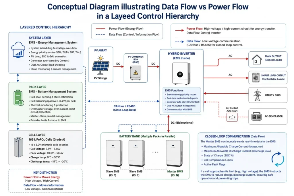
The BMS functions inside each individual battery pack, focusing on cell safety, state estimation, and physical protection. Built around 16 series-connected (16S) Grade A LiFePO4 prismatic cells (nominal voltage: 16× 3.2V = 51.2V), the BMS monitors and protects the pack:
Cell-Level Sensing: Continuously tracks individual cell voltages (operating range: 2.5V to 3.65V per cell; pack range: 40.0V to 58.4V DC).
Thermal Safeguards: Monitors cell temperatures using internal NTC thermistors. Safe charging is allowed between 0°C and 50°C, while discharging operates down to -15°C or -20°C depending on enclosure design.
Cell Balancing: Applies passive resistive balancing during upper-stage charging (>3.45V per cell) to minimize state-of-charge divergence across the 16 cells.
Master-Slave Parallel Management: In multi-pack installations—such as combining wall-mounted AL-WM512200 modules (10.24kWh each) or floor-standing mobile cabinet MB512346 units (18.0kWh each)—hardware DIP switches assign unit IDs. The Designated Master BMS aggregates status data from all Slave BMS units and acts as the single communication gateway to the hybrid inverter.
3.2 Energy Management System (EMS): System Scheduling & Strategy Execution
While the BMS protects the battery pack, the EMS operates at the system level within the hybrid inverter firmware (and cloud monitoring platforms) to direct overall energy dispatch. The EMS decides where energy goes and when. Key EMS functions include:
Executing user-configured energy priority modes (SBU, SUB, SUF, ToU).
Evaluating PV production, load demand, battery SOC, and utility grid presence in real time.
Triggering the Dry Contact auto-start relay to activate external generators when battery capacity drops below threshold limits.
Managing Dual AC Output load shedding (Main Output vs. Smart Load) during grid outages.
3.3 Closed-Loop Communication Data Flow vs. Power Circuit Flow
Distinguishing between high-voltage/high-current power circuits and low-voltage control circuits is vital during design and commissioning:
Power Circuit (Energy Flow): Heavy-gauge conductors move DC energy from PV strings through the IP65 combiner box to the inverter’s MPPT, route bidirectional DC current between the inverter and battery bank, and deliver converted AC power to site distribution panels.
Control Circuit (Data Flow): Shielded twisted-pair cables (utilizing CANbus or RS485 protocols) establish closed-loop communication between the Master BMS and the Inverter EMS.
In closed-loop mode, the BMS continuously updates the EMS with live parameters: Maximum Allowable Charge Current (Icharge_max), Maximum Allowable Discharge Current (Idischarge_max), real-time SOC %, cell temperature limits, and active fault flags. If a cell approaches its high-voltage limit, the BMS instructs the EMS to dynamically reduce charge current, preventing high-voltage disconnect trips.
| Control Layer Parameter | Battery Management System (BMS) | Energy Management System (EMS) |
| Physical Location | Integrated inside battery pack module | Embedded in hybrid inverter firmware & cloud app |
| Primary Responsibility | Cell-level safety, state estimation, pack balancing | System-level energy routing, source prioritization |
| Sensed Inputs | Cell V, Pack I, Pack T, Cell SOC/SOH | PV V/I, Grid V/F, Load demand, Battery SOC |
| Output Controls | Internal charge/discharge MOSFETs/contactors | MPPT charge rate, AC inverter output, Dry Contact relay |
| Operating Mode Logic | Agnostic to SBU/SUB dispatch strategies | Directly executes SBU, SUB, SUF, and ToU schedules |
4. Operating Strategy Execution Logic (SBU, SUB, and Off-Grid Scenarios)
The core value of an integrated Energy Hub lies in its ability to execute automated energy routing strategies based on site conditions. The EMS relies on three standardized priority frameworks.
4.1 Solar-Battery-Utility (SBU) Priority Breakdown
SBU mode maximizes solar self-consumption and off-grid independence. It treats the utility grid strictly as a backup source of last resort.
					*                 [Solar PV Power Available?]
                             │
            ┌────────────────┴────────────────┐
            ▼                                 ▼
         [YES]                               [NO]
            │                                 │
  (PV Powers Loads)             (Battery Powers Loads)
            │                                 │
 [Surplus PV Available?]           [Battery SOC > Low Limit?]
      ┌─────┴─────┐                     ┌─────┴─────┐
      ▼           ▼                     ▼           ▼
    [YES]        [NO]                 [YES]        [NO]
      │           │                     │           │
 (Charges PV) (PV+Batt)          (Batt Alone)  (Switch to
                                                Grid/Gen)
Primary Source (Solar PV): Incoming PV power feeds connected AC loads first. Any surplus PV generation is routed through the inverter’s DC charger to top up the battery bank.
Secondary Source (Battery Bank): If load demand exceeds instantaneous PV output (e.g., during cloud cover or at night), the EMS draws power from the battery bank to make up the difference.
Tertiary Source (Utility Grid / Generator): If the battery SOC drops below the configured low-capacity threshold, the EMS switches the AC load to the AC input source while preserving remaining battery energy for emergency backup.
4.2 Solar-Utility-Battery (SUB) Priority Breakdown
SUB mode prioritizes power stability and maintains maximum battery reserves for sites experiencing frequent, unpredictable grid blackouts.
Primary Source (Solar PV): PV generation powers connected loads first.
Secondary Source (Utility Grid): If solar output is insufficient to cover connected loads, the utility grid supplements the remaining demand directly. The battery bank remains unused, held at 100% SOC.
Tertiary Source (Battery Backup): The battery bank discharges to power loads only when utility grid power fails completely.
4.3 Pure Off-Grid Microgrid Dispatch Logic
In true off-grid locations where no utility grid exists, the EMS manages energy using PV generation, battery storage, and automated generator backup.
Daytime Operation: Solar PV powers active loads while charging the battery storage bank.
Nighttime Operation: The battery bank powers evening loads via the inverter.
Extended Low-Solar Protection: If consecutive overcast days drain battery storage below designated safety thresholds, the EMS triggers an external AC generator to support loads and recharge the battery bank.
5. Microgrid Resilience: Automated Generator Integration & Dry Contact Control
Integrating an auxiliary diesel or gas generator into an off-grid solar kit provides long-term energy autonomy during extended periods of low solar irradiation. Manual generator starting, however, introduces human error and operational inefficiencies. Modern off-grid ESS kits resolve this through automated passive Dry Contact control interfaces.
5.1 Passive Dry Contact Relay Logic and Trigger Thresholds
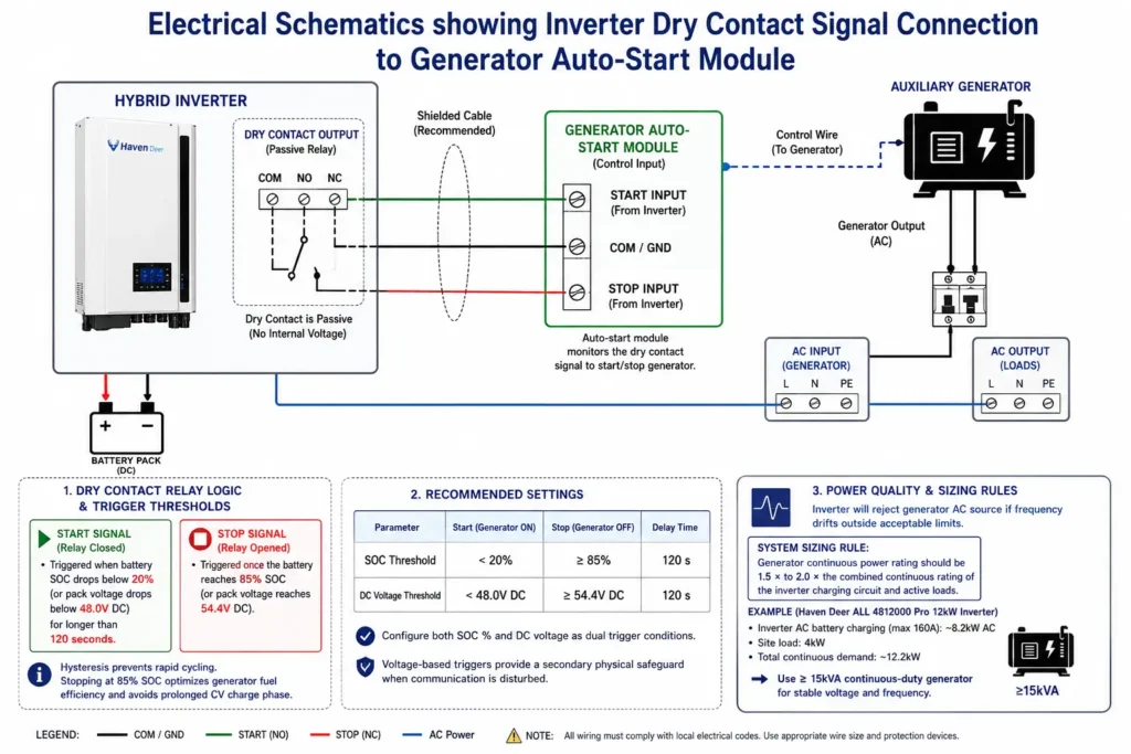
A Dry Contact is a passive relay switch within the hybrid inverter that contains no internal voltage. It acts as a remote control switch wired directly to an auto-start generator’s control module.
Engineering Tip: Configure generator auto-start triggers using both State of Charge (SOC %) and DC voltage levels. Voltage-based triggers provide a secondary physical safeguard if signal interference affects closed-loop BMS communication.
					*[Battery SOC Drops Below Lower Threshold (e.g., 20% SOC / 48.0Vdc)]
                                │
                                ▼
         [EMS Closes Dry Contact Relay (NO -> NC)]
                                │
                                ▼
   [Generator Receives Remote Start Signal & Initializes]
                                │
                                ▼
  [Inverter Detects AC Input Voltage & Frequency Stability]
                                │
                                ▼
     [AC Input Relay Closes: Generator Powers Load & Recharges]
                                │
                                ▼
[Battery SOC Reaches Upper Threshold (e.g., 85% SOC / 54.4Vdc)]
                                │
                                ▼
          [EMS Opens Dry Contact Relay (NC -> NO)]
                                │
                                ▼
 [Generator Executes Cool-Down Cycle & Shuts Down Automatically]
To prevent rapid cycling—where a generator turns on and off repeatedly near threshold points—the EMS uses a configurable hysteresis band:
Start Signal (Relay Closed): Triggered when battery SOC drops below 20% (or pack voltage drops below 48.0V DC) for longer than a set delay period (e.g., 120 seconds).
Stop Signal (Relay Opened): Triggered once the battery reaches 85% SOC (or pack voltage reaches 54.4V DC). Stopping at 85% SOC optimizes generator fuel efficiency, avoiding the prolonged low-current constant-voltage (CV) charge phase required to reach 100% SOC.
5.2 Power Quality and Inverter Frequency Tolerance Limits
Generators often output fluctuating voltage and frequency under sudden load changes. If a generator’s frequency drifts beyond acceptable boundaries, the hybrid inverter will reject the AC source to protect downstream loads.
System Sizing Rule: The continuous power rating of an auxiliary generator should be at least 1.5 × to 2.0 × the combined continuous rating of the hybrid inverter charging circuit and active loads.
For example, when using a Haven Deer ALL 4812000 Pro 12kW Inverter operating at its maximum 160A AC battery charging rate (drawing approximately 8.2kW AC) while supplying a continuous 4kW site load, the connected generator must supply at least 12.2kW continuously. A 15kVA continuous-duty generator ensures stable voltage and frequency tracking.
6. Critical Load Protection: Dual Output & UPS-Level Transfer Times
Power continuity during grid failures or generator transitions depends on fast relay switching speeds and intelligent load prioritization.
6.1 Uninterrupted Power Supply Mechanics (≤ 10 ms vs. 20 ms Switching)
When primary AC power drops, an internal high-speed transfer switch transfers connected AC loads to the bidirectional inverter operating off the battery bank.
10 ms Transfer Speed (UPS Mode): Designed for sensitive equipment such as data servers, communication terminals, security hardware, and desktop computers. A 10 ms transition occurs within a single AC cycle (16.6 ms at 60Hz; 20 ms at 50Hz), preventing power supply resets in sensitive electronics.
20 ms Transfer Speed (Standard Appliance Mode): Designed for motor-driven household appliances, HVAC units, refrigeration, and general lighting circuits.
6.2 Dual Output Architecture: Main Load vs. Smart Load Shedding
Advanced off-grid hybrid inverters—including Haven Deer 6kW and 12kW models—feature dual AC output terminals: a Main Output and a Second Output (Smart Load).
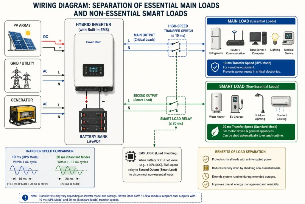
Main Output Terminal: Supplies mission-critical loads that require continuous power (e.g., refrigeration, water pumps, routers, medical devices, lighting).
Second Output Terminal (Smart Load): Supplies non-essential loads (e.g., water heaters, EV chargers, outdoor lighting, comfort cooling).
During extended outages, if the battery SOC drops below a pre-set parameter (e.g., <30% SOC), the EMS opens the internal relay feeding the Second Output. Disconnecting non-essential loads reduces total battery drain, extending run-time for essential appliances on the Main Output.
7. Compliance, Safety, and Engineering Sizing Fundamentals
A resilient off-grid solar ESS kit must comply with international electrical safety standards and use precise component sizing calculations.
7.1 IEC Certification Standards Framework (IEC 62109-1 / IEC 62109-2)
Professional installers and EPC contractors must ensure equipment meets international safety and electromagnetic compatibility benchmarks:
IEC 62109-1: Defines safety requirements for power electronic converters used in photovoltaic systems. It regulates electrical insulation, creeping distances, protection against electric shock, and thermal limits under max load.
IEC 62109-2: Dictates specific safety criteria for solar inverters, covering grid-tied and off-grid operational safety, ground-fault detection mechanisms, and isolation monitoring protocols.
EN 61000-6-1 / EN 61000-6-3: Verifies Electromagnetic Compatibility (EMC), ensuring the inverter does not emit high-frequency radio interference or suffer performance degradation near external electronics.
7.2 Basic Engineering Calculations: Energy Capacity and PV Array Sizing
Proper system design requires matching battery storage capacity and solar array power to daily consumption demands.
Formula 1: Usable Battery Storage Capacity (Eusable )
Calculate daily usable stored energy using nominal capacity, system voltage, depth of discharge, and inverter efficiency:
Where:
Cnominal = Total parallel battery bank Ah rating (e.g., 200 Ah )
Vsystem = Nominal battery bus voltage (51.2 V DC)
DoD = Recommended Depth of Discharge (80% to 90% for long cycle life)
ηinverter = Battery-to-AC discharge conversion efficiency (93% / 0.93)
Example Calculation: Calculate usable energy for a Haven Deer AL-WM512200 battery module (51.2 V, 200 Ah ) operated at 90% DoD:
Formula 2: Cold-Weather PV String Open-Circuit Voltage (Voc, max)
Photovoltaic cell voltage rises as ambient temperature drops. String calculations must ensure that maximum open-circuit voltage (Voc) never exceeds the inverter’s absolute maximum input limit (500 Vdc) at the lowest expected local temperature:
Where:
Voc, STC = Module open-circuit voltage under Standard Test Conditions (49.0 V for a 610W panel)
αVoc = Temperature coefficient of Voc (typically -0.26%/°C or -0.0026/°C)
Tmin = Site minimum winter temperature (e.g., -15° C)
Nmodules = Number of solar modules connected in series per string
Example Calculation: Calculate max voltage for a string of 8 modules (610W each) operating at -15°C:
Because 432.8 Vdc remains well below the inverter’s 500 Vdc absolute limit, an 8-panel series string operates safely within the MPPT tracker’s optimal range.
8. System Commissioning & Engineering Verification Protocols
Following a structured commissioning procedure reduces installation faults, verifies communication links, and protects system components.
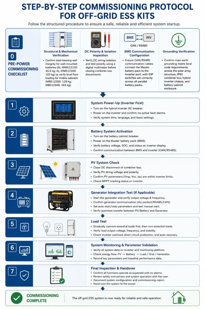
8.1 Pre-Power Commissioning Checklist
[ ] Structural & Mechanical Verification: Confirm load-bearing wall integrity for wall-mounted batteries (AL-WM512100: 45.5 kg; AL-WM512200: 102 kg) or verify level floor loading for mobile cabinets (MB512300: 129 kg; MB512346: 163 kg).
[ ] DC Polarity & Isolation Inspection: Verify DC string isolation and test polarity using a digital multimeter before closing combiner box disconnects.
[ ] BMS Communication Configuration: Ensure CAN/RS485 communication cables connect the Master battery pack to the Inverter port, with DIP switches set correctly across all parallel battery packs.
[ ] Grounding Verification: Confirm main earth grounding meets local code requirements across the solar array structure, IP65 combiner box, hybrid inverter chassis, and battery cabinet enclosure.
8.2 Sequential Power-On Sequence
Battery DC Energization: Close the main battery circuit breaker first. Wait for the battery BMS to initialize and power up the inverter’s control board.
Inverter Parameter Verification: Verify through the inverter screen or mobile monitoring app that closed-loop BMS communication is active and reading correct battery SOC %, charge current limits, and voltage values.
PV Input Energization: Close the DC isolator switches on the IP65 PV Combiner Box. Confirm the MPPT tracker detects input voltage and begins solar output.
AC Input & Generator Verification: If connected to a generator, initiate a manual dry contact test run to verify AC frequency acceptance, charger pickup, and transfer switch timing.
AC Load Branch Activation: Close AC output circuit breakers to supply distribution panels, testing dual output load shedding if configured.
9. Frequently Asked Questions (Installer & Engineer QA)
9.1 What is the fundamental difference between an off-grid solar ESS kit and a standard hybrid solar kit?
Standard hybrid systems often prioritize grid feedback and solar export. Off-grid ESS kits focus on multi-source resilience, autonomous operation without grid references, integrated generator auto-start controls, and high-speed UPS power switching ( 10 ms ).
9.2 Why is BMS logic kept separate from system EMS priority logic?
The BMS is dedicated strictly to battery pack safety, monitoring individual cell voltages, temperatures, and balancing cells. The EMS runs at the inverter level to manage overall system priorities (SBU, SUB, ToU, generator control) based on site demand and energy availability.
9.3 Can an auxiliary generator and utility grid power be connected to the inverter simultaneously?
No. In standard hybrid inverters, utility grid and generator power share the same AC input terminal block. Connecting both simultaneously without an external interlocked Automatic Transfer Switch (ATS) will cause severe equipment damage.
9.4 How fast is the transfer time when utility grid power fails?
Haven Deer hybrid inverters offer a 10 ms transfer speed for sensitive computing hardware (UPS mode) and a 20 ms transfer speed for standard household appliances.
9.5 How does the dual AC output feature preserve battery capacity during an outage?
The inverter features a Main Output for essential loads and a Second Output (Smart Load) for non-essential appliances. When battery capacity drops below configured limits during a power outage, the EMS automatically disconnects the Second Output to preserve power for critical loads on the Main Output.
9.6 Why are Grade A LiFePO4 cells preferred over lead-acid batteries in off-grid systems?
Grade A LiFePO4 cells deliver ≥ 6,000 to 10,000 operating cycles, support 80-90% Depth of Discharge, maintain high conversion efficiency, and offer intrinsic thermal stability. In contrast, lead-acid batteries suffer from short cycle life (500-1,500 cycles) and usable capacity limits (≈ 50% DoD).
9.7 How does the inverter's dry contact start an external generator?
The dry contact acts as a passive switch. When battery SOC or voltage drops below configured levels, the inverter closes the contact, sending a start signal to the generator’s auto-start controller. Once the battery reaches its upper charge limit, the relay opens, shutting down the generator.
9.8 What is the maximum PV open-circuit voltage allowed on Haven Deer inverters?
9.9 How many battery packs can be expanded in parallel?
Up to 6 battery packs (such as the 5.12kWh AL-WM512100 or 10.24kWh AL-WM512200) can be connected in parallel using standard Master-Slave BMS communication, providing up to 61.44kWh of total storage capacity.
9.10 Can Haven Deer systems operate in open-loop mode if communication cabling is damaged?
Yes. While closed-loop CAN/RS485 communication is recommended for precise SOC tracking, the system can fall back to voltage-based control modes if data links are interrupted.
9.11 What international standards govern the safety of off-grid hybrid inverters?
Haven Deer inverters comply with IEC 62109-1 and IEC 62109-2 safety standards, UL 1741 design benchmarks, and EN 61000 EMC standards.
9.12 Does Haven Deer offer custom engineering or OEM/ODM configurations for regional distributor projects?
Yes. Haven Deer provides complete OEM/ODM manufacturing, including custom equipment branding, pre-configured firmware, tailored IP65 combiner box layouts, and modular battery solutions for large-scale B2B deployments.
10. Technical Summary & B2B Engineering Support
Engineering a reliable off-grid power solution requires moving beyond standalone component selection to embrace integrated multi-source architecture. By pairing high-voltage MPPT solar regulation with Grade A LiFePO4 battery storage, closed-loop BMS/EMS control, automated generator integration, and dual AC output load management, modern off-grid ESS kits provide continuous, autonomous power across challenging operational environments.
Explore Haven Deer Off-Grid Solar ESS Kit Specifications
Request an Engineering System Review & Single-Line Diagram Pack:
Planning an off-grid residential, agricultural, or commercial microgrid project? Contact our engineering team to request customized single-line diagrams, system sizing evaluations, and technical specifications for factory-matched Haven Deer Off-Grid Solar ESS Kits.