Quick Answer: A hybrid inverter’s solar energy management system controls power dispatch for off-grid solar power system. It balances PV generation, LiFePO4 storage, grid power, and backup generators by switching operating modes and managing inverter-to-BMS communications.
1. Solar Energy Management System Architecture: How BMS and EMS Work Together in Solar ESS
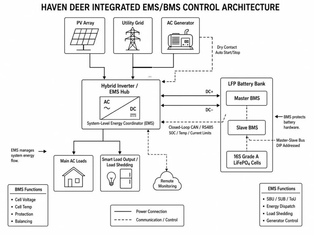
Modern solar energy storage systems (ESS) separate battery protection and system-level energy management into two coordinated control layers: the Battery Management System (BMS) and Energy Management System (EMS). Building high-reliability installations around off-grid solar power system architecture requires clear separation between these control layers.
1.1 BMS Responsibilities: Pack-Level Safety & Cell Balancing
The Battery Management System (BMS) operates directly inside each battery pack. Its primary function is safety, monitoring cell parameters to keep the battery within strict operational limits:
- Cell-Level Monitoring: Continuously measures individual cell voltages across series configurations (such as a 16S 51.2V LFP topology), pack current, and internal thermistor temperatures.
- Hardware-Level Protection: Triggers hardware cutoffs via MOSFETs or contactors during thermal or electrical faults (including <0°C charge lockout and -15°C to 50°C discharge limits).
- Cell Balancing: Controls passive or active balancing circuits to adjust State of Charge (SoC) differences across prismatic cells during the final constant-voltage (CV) phase.
- Master-Slave Bus Aggregation: Implementing a master-slave architecture for parallel battery banks ensures slave BMS units aggregate cell telemetry to the Master BMS via DIP-addressed communication lines before routing system-level data to the inverter.
The BMS is strictly a safety safeguard. It never dispatches power, sets priorities, or manages external sources.
1.2 EMS Responsibilities: System-Level Energy Dispatch & Protocol Routing
The Energy Management System (EMS) functions as the system-level energy coordination layer. Embedded within the hybrid inverter firmware and supported by remote cloud monitoring, the EMS coordinates system energy flow:
- Multi-Source Power Dispatching: Dynamically balances DC power from MPPT solar controllers, bidirectional battery charge/discharge stages, and incoming AC power from grid or generator sources.
- Operational Mode Execution: Enforces operational strategies—such as Solar-Battery-Utility (SBU), Solar-Utility-Battery (SUB), and Time-of-Use (ToU)—based on real-time generation, load demand, and battery SoC.
- External Hardware Automation: Controls hardware peripherals, including passive dry contact relays for automated generator auto-start/stop logic and dual output AC relays for load shedding.
- Protocol Translation: Processes high-speed CAN Bus or RS485 telemetry from the Master BMS, translating battery telemetry into dynamic charge and discharge current limits for inverter control (I_max_charge, I_max_discharge).
Engineering Insight
BMS and EMS are complementary control layers, not competing systems. The BMS protects battery cells by enforcing safety limits, while the EMS optimizes overall energy flow between PV, battery, grid, generator, and loads. Reliable ESS performance depends on accurate communication and coordinated control between these two layers.
| Control Feature / Attribute | Pack-Level BMS (Battery Protection) | System-Level EMS (Energy Coordination) |
| Primary Physical Location | Integrated Protection Board on Battery Module | Hybrid Inverter Firmware (with Optional Cloud Monitoring) |
| Control Scope | Individual Prismatic Cells & Series Battery Modules | PV Array, Inverter, Grid, Generator & Loads |
| Monitored Variables | Cell Voltage, Pack Voltage, Cell Temperature, MOS Temp | PV Input Voltage/Current, Grid Hz/V, Load kW, System SoC |
| Primary Output Action | Operates Charge/Discharge MOS Relays, Cell Balancing | Controls inverter operating strategy, AC relays, and energy dispatch commands |
| Priority Decision Logic | None (Executes safety cutoffs only) | Enforces SBU, SUB, ToU, Peak Shaving Priority Logic |
| Communication Layer | Master-Slave Internal Bus (DIP Addressed) | CAN Bus, RS485 for inverter-battery communication; Wi-Fi/4G for remote monitoring |
1.3 Real-World Engineering Scenario: BMS Protection and EMS Coordinated Response
Consider a 12kW hybrid solar ESS installation where the battery bank experiences elevated cell temperature during a high-power charging period. When a battery cell temperature approaches the protection threshold, the Master BMS detects the abnormal condition and transmits the warning status to the hybrid inverter through CAN communication.
Instead of allowing the battery protection event to interrupt the entire energy system, the EMS receives the BMS protection signal and adjusts the charging strategy according to the available battery limits. The inverter reduces or stops battery charging current, while redirecting available PV energy to connected AC loads or other permitted energy paths.
This BMS-EMS handshake preserves battery safety while preventing unnecessary system shutdowns.
In Haven Deer hybrid architectures, such as the ALL 486000 Pro and ALL 4812000 Pro hybrid solar inverters, this two-tiered structure ensures system protection. The BMS safeguards the battery hardware, while the co-engineered EMS manages system performance.
2. Multi-Input Energy Dispatching Logic: Managing 4 Distinct Power Sources
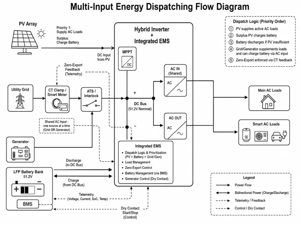
Direct System Routing Logic: The integrated EMS routes energy across PV, battery, grid, and generator inputs. It treats PV as the primary renewable DC input, the battery bank as a bidirectional DC buffer, and the AC input port as a switchable connection for utility grid or generator sources.
2.1 PV Generation & Dynamic MPPT Allocation
The hybrid inverter processes solar energy through high-efficiency Maximum Power Point Tracking (MPPT) channels while the EMS controls allocation to loads, battery charging, and auxiliary paths. Operating across wide DC voltage windows (60–500V DC on dual-tracker 12kW models and 120–500V DC on 6kW models), applying single vs dual MPPT tracker optimization allows the power stage to adjust duty cycles and extract maximum yield under mismatched string conditions. The EMS routes PV energy using a strict priority order:
- Direct DC-to-AC conversion to supply active AC loads.
- Conversion through the DC-DC stage to charge the battery bank up to configured current limits.
- Routes excess PV power to secondary battery charging or grid interaction based on site parameters.
2.2 Bidirectional Battery Storage Flow (Charge vs. Discharge)
The battery storage system functions as a bidirectional energy reservoir on the 48V (51.2V nominal) DC bus:
- Charging Mode: When PV generation exceeds load consumption, the EMS directs surplus power into the battery through a CC/CV (Constant Current / Constant Voltage) profile governed by BMS telemetry.
- Discharging Mode: When PV output falls below load demand, the EMS commands the battery power stage to discharge energy through the DC bus and support the DC-AC inverter stage.
2.3 Utility Grid Integration & Grid-Support Boundaries
When connected to active utility power, the EMS monitors grid voltage (220/230/240V AC) and frequency (50/60Hz). Nominal grid parameters trigger the internal pass-through relay. The grid can act as an auxiliary power source or charge the battery according to configured operating modes, such as scheduled off-peak charging under Time-of-Use (ToU) strategies.
Engineering Rule on Grid Export Limits: To satisfy IEEE 1547 grid-interconnection standards, an integrated EMS cannot execute zero-export control using internal inverter measurements alone. To prevent unauthorized power feed-in to the utility grid, an external Current Transformer (CT) clamp or Smart Meter must be installed at the main utility service entrance, providing real-time bidirectional current telemetry to the EMS control loop.
2.4 Generator Integration via Shared AC Input Port
Single-phase and split-phase hybrid inverters share one AC Input terminal block for grid and generator connections. Internal hardware cannot accept two unsynchronized AC sources simultaneously.
Consequently, the EMS treats the AC Input as a switchable source port. An external Automatic Transfer Switch (ATS) or interlock relay must ensure that grid power and generator output never energize the inverter terminals at the same moment. When grid power fails and battery SoC reaches configured thresholds, the EMS fires a dry contact signal to start the generator. The hybrid inverter then adjusts its operating parameters to match the available generator power curve.
2.5 System Power Balance Model: Energy Flow Relationship
At any instantaneous point in time t, the integrated EMS enforces continuous power balance across the system according to the following equation:
P_PV(t) + P_Bat_Discharge(t) + P_Grid/Gen_In(t) = P_Load_Main(t) + P_Load_Smart(t) + P_Bat_Charge(t) + P_Losses(t)
Where:
- P_PV(t) = Instantaneous power generated by solar array (kW)
- P_Bat_Discharge(t) = Power drawn from battery bank (kW)
- P_Grid/Gen_In(t) = Power drawn from Utility Grid or AC Generator (kW)
- P_Load_Main(t) = Active power consumed by essential main AC loads (kW)
- P_Load_Smart(t) = Active power consumed by non-essential smart AC loads (kW)
- P_Bat_Charge(t) = Power directed into battery charging (kW)
- P_Losses(t) = Thermal and conversion losses across power stages (kW)
Worked Calculation Example: A commercial site equipped with a Haven Deer ALL 4812000 Pro inverter experiences peak midday sun (P_PV = 10.0kW). Connected site loads draw P_Load_Main = 4.0kW. Assuming an overall conversion loss of approximately 0.4kW during power conversion, the remaining energy is available for battery charging.
Substituting into the power balance equation with P_Grid/Gen_In = 0kW and P_Load_Smart = 0kW:
10.0 kW + 0 kW + 0 kW = 4.0 kW + 0 kW + P_Bat_Charge(t) + 0.4 kW
P_Bat_Charge(t) = 10.0 – 4.0 – 0.4 = 5.6 kW
Expressed in DC charging current for a 51.2V battery bank:
I_Charge = 5600 W / 51.2 V = 109.37 A
The hybrid inverter charging stage delivers approximately 109.4A of DC charging current to the battery bank, remaining within the 160A maximum charging capability of the ALL 4812000 Pro.
| Operational Scenario | PV Array Status | Utility Grid / Generator | Battery Status | Power Dispatch Path |
| Daytime Surplus | P_PV > P_Load | Grid Standby / Isolated | Charging (P_Surplus -> Bat) | PV powers AC Loads directly; surplus charges Battery bank. |
| Night Normal | P_PV = 0 | Grid Standby (SBU Mode) | Discharging to AC Load | Battery discharges through DC-AC inverter stage to support Loads. |
| Cloudy / Low Solar | P_PV < P_Load | Grid Supplementing | Standby / Slow Discharge | PV and Grid combine to supply connected AC loads under hybrid modes. |
| Off-Grid Outage | P_PV = 0 | Generator Active | Recharging from Gen | Generator powers Main Loads and charges Battery bank via EMS. |
| High Load Peak | P_PV + P_Bat < P_Peak | Grid Supplying Peak | Maximum Discharging | PV, Battery, and Grid share high-demand loads up to inverter rating. |
Engineering Insight
Multi-input energy management goes beyond wiring multiple sources. The hybrid inverter coordinates energy priority, battery protection limits, AC source availability, and load demands through configured operating modes. Reliable off-grid performance depends on control logic, not source count.
3. Core EMS Operating Modes: SBU, SUB, ToU, and Peak Shaving
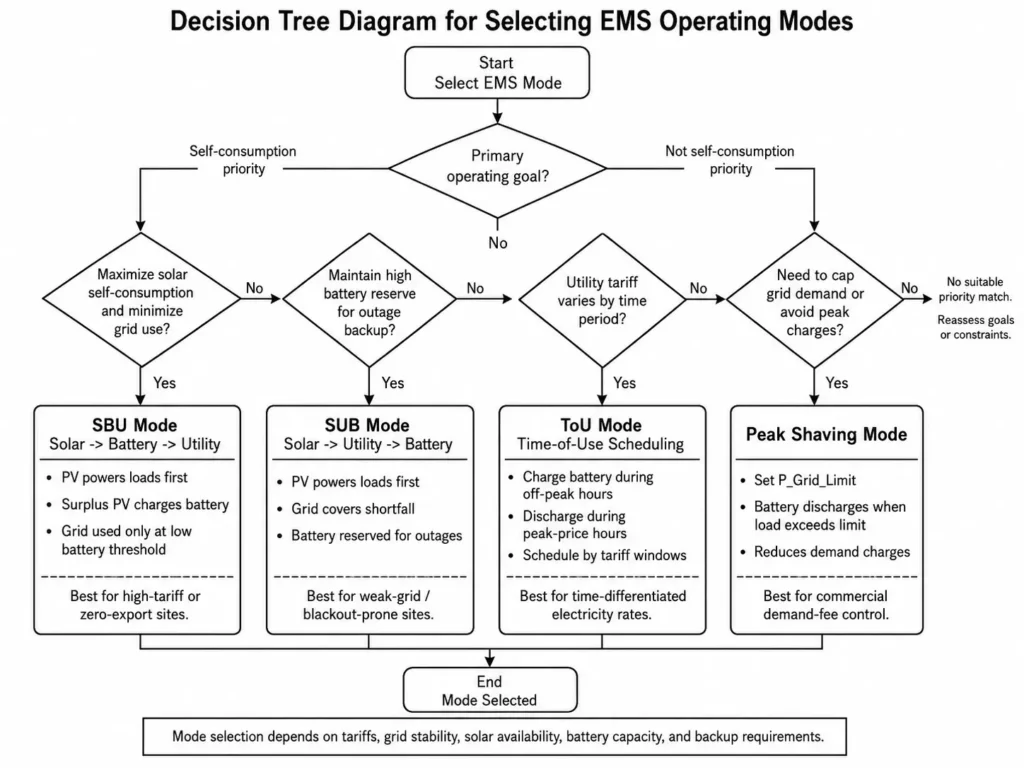
Direct Operating Summary: EMS operating modes define energy prioritization across available sources. SBU mode prioritizes Solar, then Battery, using the Grid as a backup source when battery conditions reach configured limits. SUB mode prioritizes Solar, then Grid, maintaining Battery reserve for backup operation. ToU mode schedules battery charging and discharging based on utility tariff periods, while Peak Shaving reduces grid demand by using available battery power during high-load periods.
3.1 SBU Mode (Solar -> Battery -> Utility): Self-Consumption Priority
In SBU (Solar-Battery-Utility) mode, the system minimizes utility reliance:
- Solar First: PV energy powers connected loads first. Surplus PV charges the battery bank.
- Battery Second: When PV is unavailable or insufficient, the battery discharges to cover load demand.
- Utility Last: Utility grid power kicks in only when battery voltage or SoC hits low threshold limits.
SBU mode fits high-tariff regions or zero-export sites to maximize solar self-consumption.
3.2 SUB Mode (Solar -> Utility -> Battery): Grid Backup Priority
In SUB (Solar-Utility-Battery) mode, the system prioritizes battery reserve:
- Solar First: PV energy powers connected loads first.
- Utility Second: If PV generation is insufficient, utility grid power supplements the shortfall directly.
- Battery Last: The battery maintains a high reserve SoC and discharges only during grid outages.
Deploying off-grid power solutions for weak-grid commercial sites often relies on SUB mode to maintain high battery reserve levels for emergency backup while offsetting daytime loads with PV.
3.3 Time-of-Use (ToU) & Peak Shaving Algorithms
Modern smart grids require flexible scheduling:
- Time-of-Use (ToU): Installers program time windows matching local utility tariff schedules. During low-cost off-peak hours (e.g., 00:00 to 06:00), the EMS charges the battery bank from the grid. During high-cost peak hours (e.g., 17:00 to 21:00), the EMS reduces grid consumption by discharging the battery according to configured schedules.
- Peak Shaving Mode: For light commercial facilities with strict maximum demand limits, the installer sets a maximum grid power ceiling (P_Grid_Limit). Whenever site consumption exceeds this value, the EMS commands battery discharge to supply part of the load demand, reducing grid power draw and limiting peak demand charges.
| Parameter / Feature | SBU Mode (Self-Consumption) | SUB Mode (Grid Priority Backup) | ToU (Time-of-Use Scheduling) | Peak Shaving Mode |
| PV Generation Target | 1st: Load; 2nd: Battery | 1st: Load; 2nd: Grid | 1st: Load; 2nd: Battery | 1st: Load; 2nd: Battery |
| Secondary Supply Source | Battery Storage Bank | Utility Grid | Grid/Battery According to Tariff Schedule | Battery Supplementation |
| Battery Reserve Status | Cyclically Discharged Daily | Maintained at Configured High SoC Reserve | Discharged during Peak Tariff | Discharged during Power Spikes |
| Grid Power Dependency | Minimal (Emergency Backup Only) | Configurable According to Backup Strategy | Configurable by Schedule | Capped at P_Grid_Limit |
| Target Application | High Electricity Rates / Solar ROI | Weak Grids / Frequent Blackouts | Time-Differentiated Electricity Rates | Commercial Demand Fee Avoidance |
3.4 Practical Engineering Example
A small commercial workshop in an area with an unstable grid operates heavy machinery during the day. Configuring the EMS to SUB mode allows daytime solar generation to offset part of the workshop’s energy demand while utility power supports additional load requirements when needed. The 10.24kWh Haven Deer battery bank is maintained at a configured backup reserve level. When an afternoon grid outage occurs, the hybrid inverter switches to battery backup operation according to configured transfer settings, maintaining continuous power supply for critical loads.
Engineering Insight
EMS operating modes are configurable energy management strategies rather than static hardware paths. Optimal mode selection depends on tariffs, grid stability, solar availability, battery capacity, and backup requirements. Mode selection dictates system ROI and backup reliability.
4. Automated Generator Integration & Passive Dry Contact Logic
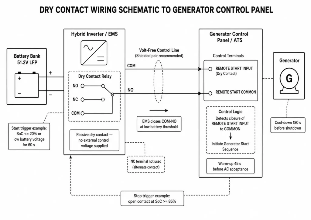
Direct Signal Trigger Answer: The EMS executes automated generator integration via passive dry contact logic using volt-free relay switching (Normally Open / Normally Closed) to electrically isolate control circuits. When battery SoC or voltage drops to the start threshold, the EMS closes the dry contact, signaling the generator controller or ATS to initiate autostart.
4.1 Dry Contact Relay Mechanics and Signal Triggering
The dry contact port on a hybrid inverter functions as a passive volt-free switch and does not provide external control voltage. It provides electrical isolation between inverter control electronics and external generator control circuits. Actual relay ratings and wiring requirements depend on the inverter model and generator controller specifications.
+-----------------------------------------------------------------------------------+
| HYBRID INVERTER DRY CONTACT CONTROL INTERFACE                                     |
+-----------------------------------------------------------------------------------+
|                                                                                   |
|                              [ Hybrid Inverter Board ]                            |
|                                          │                                        |
|                                 (Dry Contact Port)                                |
|                                                                                   |
|                     [ NO ]            [ NC ]          [ COM ]                     |
|                        │                                   │                      |
|                        └─────────────────┬─────────────────┘                      |
|                                          │  (Volt-Free Control Line)              |
|                                          ▼                                        |
|                      [ Generator Auto-Start Controller / ATS ]                    |
|                                                                                   |
+-----------------------------------------------------------------------------------+
When the EMS determines generator support is required, configured trigger thresholds dictate when the relay changes state between Common (COM) and Normally Open (NO) terminals. This closed-loop signal instructs the external generator controller or ATS to begin the configured start sequence.
4.2 SoC % vs. Voltage-Based Trigger Thresholds & Warm-up/Cool-down Cycles
Properly setting dry contact trigger thresholds prevents engine short-cycling, mechanical wear, and unneeded fuel consumption by establishing an SoC hysteresis band with defined timing delays:
Generator Stop Trigger: The EMS opens the dry contact once the battery reaches its target SoC, voltage threshold, or run-timer limit.
Generator Start Trigger: The EMS initiates a generator start request when battery parameters drop to set limits (e.g., low SoC or low battery voltage) for a continuous programmed duration.
+-----------------------------------------------------------------------------------+
| BATTERY SOC HYSTERESIS & GENERATOR CONTROL LOGIC                                  |
+-----------------------------------------------------------------------------------+
|                                                                                   |
|  Battery SOC (%)                                                                  |
|   100% ┤                                                                          |
|    85% ┼─────────────────────────────────┐ (Engine OFF Signal Sent)               |
|        │                                 │                                        |
|        │    Generator Charging Phase     │ ◄── [ Engine Cool-Down Delay ]         |
|        │                                 │                                        |
|    20% ┴─┐ (Dry Contact Closes / ON)    ─┘                                        |
|          │                                                                        |
|          └── [ Engine Warm-Up Delay ]                                             |
|                                                                                   |
+-----------------------------------------------------------------------------------+
The sequence follows four key stages:
- Start Signal Delay: The battery must remain below the start threshold for a continuous programmed duration (e.g., 60 seconds) to prevent false triggers from temporary motor inrush currents.
- Engine Warm-up Cycle: Once the generator starts, the system allows an appropriate warm-up period for engine speed, frequency, and output voltage stabilization before accepting generator AC input.
- Bulk Recharging: The EMS accepts generator AC input, directing power to satisfy active loads and recharge the battery bank at the programmed AC charge rate.
- Cool-down Cycle: When the battery reaches the stop threshold (e.g., 85% SoC), the EMS opens the relay. The generator controller then runs its programmed cool-down cycle before engine shutdown.
| Parameter Field | Recommended LFP Setting (51.2V Nominal) | Engineering Purpose / Constraint |
| Dry Contact Start Threshold | Example Configuration: 20% SoC (or voltage threshold) | Prevents deep discharge while leaving capacity for emergency loads. |
| Dry Contact Stop Threshold | Example Configuration: 85% SoC (or voltage threshold) | Balances backup readiness with charging efficiency according to battery configuration. |
| Start Signal Delay Time | 60 Seconds | Filters out temporary voltage dips caused by motor start currents. |
| Generator Warm-Up Time | 45 Seconds | Allows engine RPM and output frequency to stabilize before load connection. |
| Generator Cool-Down Time | 180 Seconds | Prevents engine damage caused by heat soak after running under high load. |
| Max AC Charging Current | Configured per generator capacity, inverter charger, and battery | Matches generator kVA capacity to prevent engine overloading. |
4.3 Practical Engineering Scenario
A remote telecom microgrid powered by a Haven Deer MB512300 (15.0kWh off-grid solar battery) experiences three consecutive overcast days. When battery SoC hits the 20% start threshold, the inverter EMS closes the dry contact relay to signal the generator controller. The auxiliary diesel generator starts, warms up for 45 seconds, and begins supplying AC power. The EMS charges the battery back to 85% SoC over a continuous 2.5-hour run. Upon hitting 85% SoC, the EMS opens the dry contact, allowing the generator controller to execute its programmed cool-down and shutdown sequence.
Engineering Insight
A dry contact interface does not directly power or control a generator engine. It provides a simple and reliable communication signal between the hybrid inverter and the generator control system. Dry contacts provide signal triggers—they never supply control voltage.
5. Dual AC Output Engineering & 10ms UPS Transfer Mechanics
Direct Load Shedding Logic: Dual AC Output architecture isolates essential backup loads from heavy non-essential equipment. During a grid outage, the hybrid inverter maintains power to the Main AC Output while the EMS manages the Second AC Output (Smart Load) based on battery SoC and load limits.
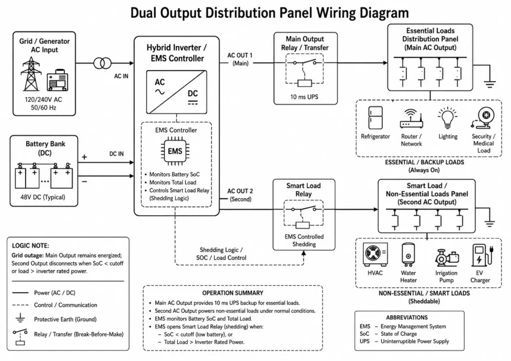
5.1 Critical Load Protection (Main Output) vs. Smart Load Shedding (Second Output)
Standard single-output inverters force installers to choose between backing up the entire panel (risking instant overload) or isolating a few sub-circuits, whereas implementing dual AC output engineering solves this constraint by splitting loads across two independently managed output terminals:
Second AC Output (Smart Load): Powers heavy non-essential loads (HVAC, water heaters, irrigation pumps, EV chargers). During a grid outage, the EMS energizes this output only when battery SoC and inverter load capacity remain within safe limits. If battery SoC drops below the cutoff limit, the EMS trips the Smart Load relay to preserve runtime for critical loads on the Main Output.
Main AC Output (Essential Loads): Supplies mission-critical loads (refrigerators, networking equipment, security systems, lighting, medical devices). The inverter maintains continuous power to this port during outages until the battery hits its minimum cutoff threshold.
5.2 Phase Synchronization and 10ms/20ms Switching Parameters
To execute seamless transfer, the inverter uses Phase-LockProperly understanding 10ms UPS transfer time relies on evaluating how Phase-Locked Loop (PLL) algorithms mirror utility AC voltage, frequency, and phase angle before a disconnect event occurs.
+-----------------------------------------------------------------------------------+
| 10ms UPS SWITCHING TIMING & PHASE-LOCKED INJECTION                                |
+-----------------------------------------------------------------------------------+
|                                                                                   |
|  Grid Line Voltage (Vac)                                                          |
|   ───┐                               ┌─── Line Disconnect Event                   |
|      └───┐                       ┌───┘                                            |
|          └───┐               ┌───┘                                                |
|  ────────────┼───────────────┼──────────── Time (ms)                              |
|              │  10ms Window  │                                                    |
|  Inverter AC Output (Vac)    │                                                    |
|              ├───┐       ┌───┤ ◄── Phase-Locked Inverter Injection                |
|                  └───┘                                                            |
|                                                                                   |
+-----------------------------------------------------------------------------------+
- 10ms UPS Setting: Designed for sensitive electronics like servers, workstations, and network gear. The inverter switches from grid to battery in under 10ms, preventing sensitive equipment from rebooting.
- 20ms Transfer (Appliance Setting): Suitable for standard household appliances where a slightly longer switching window prevents nuisance tripping during minor voltage sags.
5.3 Mathematical Smart Load Shedding Condition
Smart Load Disconnect Condition Example: Disconnect Second Output when Grid_Status = OFF and (Battery_SoC < SoC_Cutoff OR Total_Load > P_Inverter_Rated).
Worked Smart Load Calculation: A residential installation utilizes a 6kW Haven Deer ALL 486000 Pro inverter (P_Inverter_Rated = 6,000W). Connected loads total 7,500W: 4,000W of essential circuits on the Main Output and 3,500W of air conditioning on the Smart Load Output.
When a utility grid outage occurs:
- Total connected load (7,500W) exceeds rated inverter continuous capacity (6,000W).
- Powering both outputs simultaneously would trigger an instantaneous inverter overload trip.
- The EMS detects grid loss and immediately opens the Smart Load relay, dropping the 3,500W HVAC load.
- The Main Output maintains power to the 4,000W essential load, running comfortably within the inverter’s 6,000W continuous rating.
| Output Terminal | Connected Load Priority | Outage Transfer Time | Shedding Trigger Logic | Typical Equipment Connected |
| Main AC Output | High Priority (Essential) | Up to 10ms (Model Dependent) | Maintained continuous backup until battery reaches minimum discharge cutoff. | Routers, Servers, Refrigerators, Security Cameras, Medical Devices |
| Second AC Output | Low Priority (Smart Load) | 10–20ms | Sheds instantly on grid failure or when battery SoC drops below cutoff limit. | Central AC, Water Heaters, EV Chargers, Submersible Well Pumps |
Engineering Insight
Dual AC Output architecture converts passive backup storage into active load control. Smart shedding extends critical runtime without oversized battery banks.
6. Closed-Loop BMS-EMS Communication & Signal Protocols
Direct Protocol Answer: Closed-loop communication links the battery BMS to the inverter EMS via CAN Bus or RS485. Instead of estimating capacity via terminal voltage, the inverter receives live battery telemetry—including SoC, cell voltages, temperatures, and dynamic current limits.
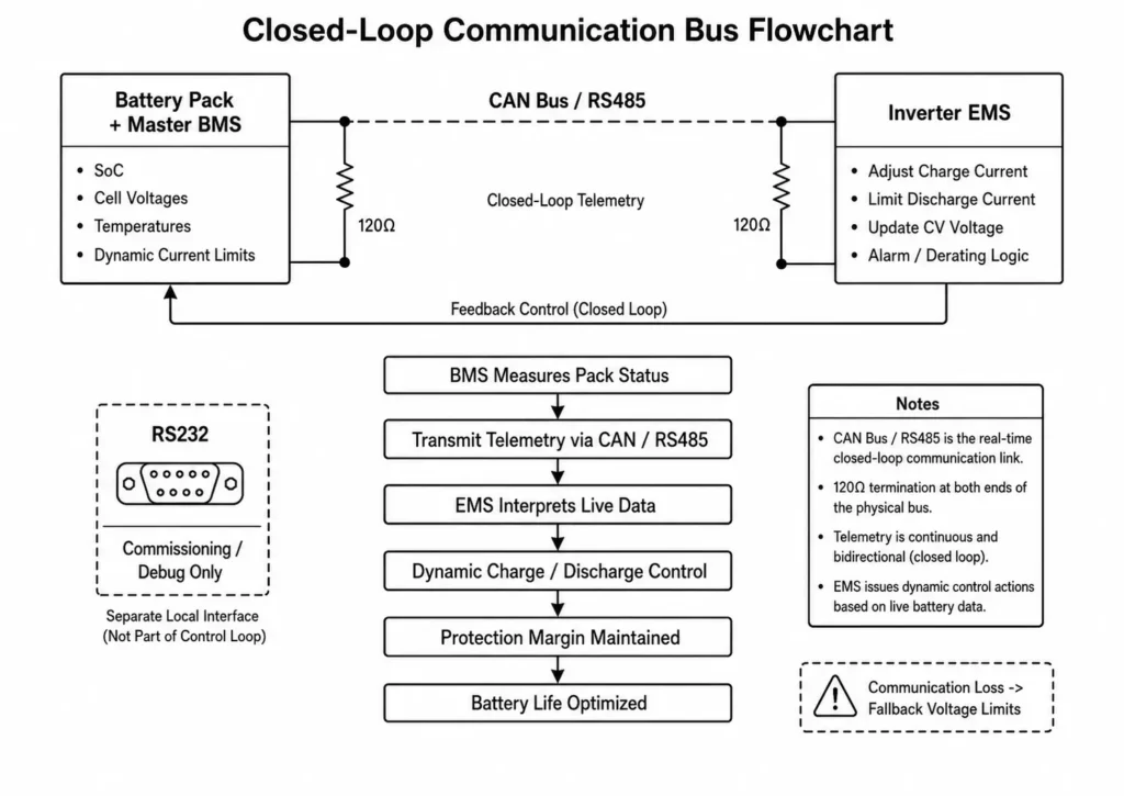
6.1 Physical Layer Protocols: CAN Bus vs. RS485 vs. RS232
Selecting the appropriate physical communication interface is critical for control stability:
- Adopting CAN Bus protocol standards defined under ISO 11898 ensures high-speed differential noise immunity for critical inverter-to-battery links. CAN offers strong noise immunity, hardware-level error checking, and fast frame transmission.
- Implementing Modbus RTU specification standards via RS485 enables reliable differential multi-drop telemetry across parallel battery packs and external monitoring hubs. Its multi-drop architecture cleanly supports multi-pack configurations.
- RS232: Single-ended serial interface reserved for local commissioning, firmware flashes, or field debugging. It is not used for real-time inverter control loops.
Engineering Tip — CAN Bus Termination: CAN networks require 120Ω termination resistors at both physical ends of the bus to maintain signal integrity. On supported Haven Deer battery models, termination resistors are toggled via onboard DIP switches. Omitting termination causes signal reflection, packet corruption, and communication drops under high EMI conditions.
6.2 Open-Loop vs. Closed-Loop Operation: Impact on Charging Profiles
Evaluating open-loop vs closed-loop BMS-inverter communication reveals clear operational impacts on dynamic charge profiles, protection margins, and battery cell longevity:
+-----------------------------------------------------------------------------------+
| CLOSED-LOOP CAN CONTROL VS OPEN-LOOP FALLBACK TOPOLOGY                            |
+-----------------------------------------------------------------------------------+
|                                                                                   |
|  [ Closed-Loop CAN Control ]                                                      |
|  Master BMS ──► Real-Time Telemetry ──► Inverter EMS ──► Dynamic Current Control  |
|  (16S Cell V/T)   (Max 160A / Max V)    (Exact Control)   (Long Battery Life)     |
|                                                                                   |
|  [ Open-Loop Fallback ]                                                           |
|  Inverter EMS ──► Estimates SOC via Voltage ──► Fixed Voltage Cutoffs             |
|  (No Cell Telemetry) (Subject to Voltage Drift)  (Risk of Premature Cutout)       |
|                                                                                   |
+-----------------------------------------------------------------------------------+
Closed-Loop Control: The BMS transmits real-time cell parameters and dynamic current limits to the inverter. If a single cell approaches its upper voltage limit, the inverter throttles charging current before the BMS trips its protection MOS/contactor. Dynamic throttling prevents nuisance BMS trips, maximizes charge acceptance, and extends cell cycle life.
Open-Loop Control: The inverter operates blind to internal cell states, estimating capacity strictly from terminal voltage. Because LiFePO4 has a flat voltage curve, open-loop SoC estimation drifts under dynamic loads, risking premature low-voltage cutoffs or overcharging.
| BMS Communication Protocol Register Field | Data Type Transmitted | EMS Firmware Execution Action |
| Max_Charge_Current_Limit (I_Charge_Max) | Dynamic Amperage Limit (A) | Limits total charging current applied by the inverter based on cell temperature and SoC limits. |
| Max_Discharge_Current_Limit (I_Discharge_Max) | Dynamic Amperage Limit (A) | Caps maximum inverter DC current draw during peak load demand. |
| Battery_Charge_Voltage_Set (V_CV_Target) | Voltage Target (V DC) | Adjusts constant-voltage (CV) absorption setpoint dynamically (typically 56.0V). |
| Real-time_Pack_SOC | Percentage (0–100%) | Updates EMS operating logic, monitoring displays, ToU schedules, and generator autostart triggers. |
| Alarm_Flags (Over-Temp / Cell Imbalance) | Bitmask Array | Initiates dynamic current derating or triggers smart load shedding. |
If closed-loop communication drops, the inverter defaults to configured fallback voltage limits, issuing communication alerts to maintain safe operation until signal recovery.
Engineering Insight
Closed-loop communication turns static safety cutoffs into dynamic power control.
7. Engineering Sizing & Commissioning Framework for Integrated EMS
Direct Commissioning Summary: Hybrid ESS commissioning requires validating wiring, battery communication, protection limits, and EMS operating profiles before energizing loads. Combining a step-by-step engineering guide to sizing off-grid ESS kits with a structured commissioning checklist prevents field errors such as undersized battery banks, incorrect dry contact wiring, and communication drops.
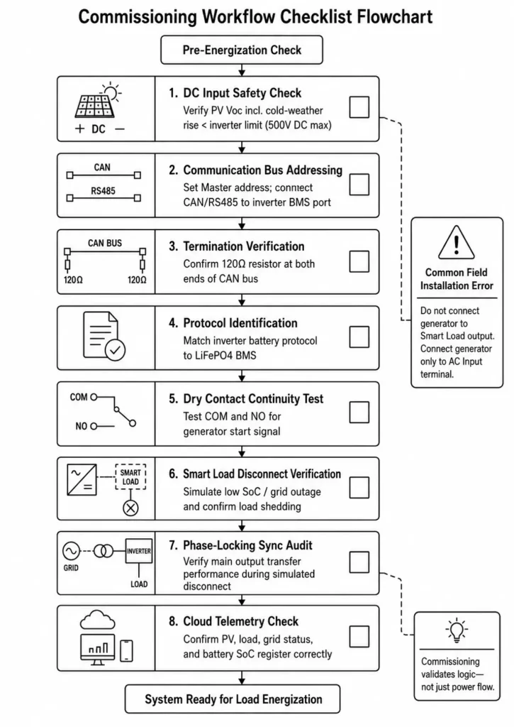
7.1 Commissioning Parameter Matrix for Off-Grid and Weak-Grid Sites
Before applying system power, following a standardized commissioning checklist for installers via the inverter display or mobile app ensures accurate EMS logic setup and protection verification:
+-----------------------------------------------------------------------------------+
| SYSTEM COMMISSIONING & EMS LOGIC SETUP FLOW                                       |
+-----------------------------------------------------------------------------------+
|                                                                                   |
|  [Phase 1: Isolation Check]                                                       |
|  (Verify PV Voc Within Inverter Limit)                                            |
|        │                                                                          |
|        ▼                                                                          |
|  [Phase 2: Comm Link Setup]                                                       |
|  (Set Master Address)                                                             |
|        │                                                                          |
|        ▼                                                                          |
|  [Phase 3: EMS Logic Commissioning]                                               |
|  (Select SBU / SUB / ToU Mode)                                                    |
|                                                                                   |
+-----------------------------------------------------------------------------------+
7.2 8-Point EMS Field Commissioning Checklist
- [ ] 1. DC Input Safety Check: Confirm total PV string Open Circuit Voltage (Voc), including cold-weather voltage rise, remains below inverter limits (500V DC max for ALL 4812000 Pro and ALL 486000 Pro).
- [ ] 2. Communication Bus Addressing: Set Master battery communication address and connect CAN/RS485 wiring to the inverter BMS port.
- [ ] 3. Terminal Resistance Verification: Confirm 120Ω CAN termination resistors are engaged at both ends of the communication bus.
- [ ] 4. Protocol Identification: Configure the inverter battery protocol setting to match the connected LiFePO4 BMS profile.
- [ ] 5. Dry Contact Continuity Test: Check continuity across COM and NO terminals when manually triggering a generator test start.
- [ ] 6. Smart Load Disconnect Verification: Confirm Smart Load output sheds when simulating low SoC or grid outage events.
- [ ] 7. Phase-Locking Sync Audit: Verify Main Output transfer performance matches inverter specifications during simulated grid disconnect tests.
- [ ] 8. Cloud Telemetry Check: Verify real-time PV generation, load power, grid status, and battery SoC register accurately on the monitoring portal.
Common Field Installation Error: Never connect a generator to the Second AC Output (Smart Load) terminal. Backfeeding AC power into the Smart Load port destroys the inverter output stage. Connect generators exclusively to the shared AC Input terminal.
| Error Code / Symptom | Root Electrical Cause | Field Diagnostic & Corrective Action |
| BMS Communication Warning | Incorrect DIP address; damaged CAN cable; missing 120Ω termination. | Verify Master battery communication address; check CAN/RS485 pinouts; confirm bus termination DIP switch settings. |
| Generator Fails to Auto-Start | Open-circuit dry contact wiring; incorrect start threshold or delay timer. | Test dry contact terminals with a multimeter; verify SoC start threshold and signal delay timers. |
| Inverter Drops Sensitive Loads | Inverter mode or transfer setting mismatched to load sensitivity. | Update inverter system settings to enforce 10ms UPS transfer capability. |
| Smart Load Sheds Instantly | Smart Load disconnect SoC threshold set too high; total load exceeds rating. | Adjust Smart Load cutoff thresholds and rebalance circuits if load demand exceeds continuous capacity. |
Engineering Insight
Commissioning validates logic—not just power flow.
8. Frequently Asked Questions
Q1: How does an integrated EMS decide whether to charge the battery from PV or Grid?
The selected EMS operating mode dictates charging priority. In SBU mode, PV energy powers loads and charges the battery first; grid charging triggers only when battery voltage or SoC drops below cutoff limits. In SUB or ToU modes, grid charging follows scheduled off-peak windows or low-PV thresholds.
Q2: What is the primary functional difference between BMS and EMS?
The BMS safeguards battery cells (pack-level safety), while the EMS dispatches power across PV, battery, grid, and generator inputs (system-level routing).
Q3: Can an integrated EMS operate a generator and grid connection simultaneously on the same inverter?
No. Single-phase and split-phase hybrid inverters share one AC input terminal block for grid and generator connections. An external ATS or interlock switch must prevent simultaneous AC connections to avoid destroying the inverter control stage.
Q4: How fast does the EMS switch to battery backup during a power outage?
Haven Deer hybrid inverters execute a 10ms transfer for UPS-grade loads (preventing server reboots) and 20ms for standard household appliances.
Q5: What happens if CAN communication between BMS and EMS breaks?
The inverter drops into open-loop fallback mode, triggering a comms alarm and enforcing conservative voltage cutoffs to protect the battery until connection restores.
Q6: How does dry contact generator control prevent engine short-cycling?
The EMS enforces SoC hysteresis and timing delays (e.g., 60-second start delay, 180-second cool-down). This prevents rapid cycling from momentary voltage sags or load surges.
Q7: Can integrated EMS limit grid feedback (zero export) without external meters?
No. Zero-export control requires a Current Transformer (CT) clamp or Smart Meter at the main service entrance to feed live current telemetry back to the EMS loop.
Q8: What is Dual AC Output and how does it extend battery backup time?
Dual AC Output isolates essential circuits (Main) from sheddable loads (Smart Load). During a blackout, the EMS trips the Smart Load relay when battery SoC drops below cutoff, reserving remaining capacity for critical loads.
Q9: How does EMS manage high motor surge currents from pumps or air conditioners?
The inverter’s power stage absorbs inductive inrush currents (up to 2x rated output for 5–10 seconds) using instantaneous battery discharge, avoiding AC output tripping.
Q10: Why is Grade A LiFePO4 chemistry recommended for EMS fast-charging?
Grade A prismatic cells feature low internal resistance and tight capacity matching. This allows high C-rate charging (up to 160A on Haven Deer 12kW units) without triggering individual cell overvoltage or thermal BMS trips.
Q11: What is the role of EMS in a hybrid solar energy storage system?
The EMS is the system power router. It controls energy priorities, switches operating modes, and processes BMS telemetry to dispatch power across PV, battery, grid, generator, and loads.
9. Request an Engineering System Review & Single-Line Diagram
Building a residential, commercial, or off-grid ESS project? Haven Deer provides application engineering support for system integrators, EPC contractors, and solar distributors to validate system topology, communication protocols, and EMS logic before field deployment.
Our Engineering Review Support Includes:
- Single-Line Diagram (SLD) Review: Validates multi-input hybrid ESS topologies, protection ratings, and bus sizing.
- Control Logic Configuration: Assesses dry contact generator auto-start wiring and Smart Load shedding parameters.
- PV String Sizing Verification: Calculates Open Circuit Voltage (Voc) cold-weather temperature correction and MPPT input limits.
- Custom OEM/ODM Integration: Tailors hybrid inverter and battery cabinet configurations to project-specific requirements.
Request Your Engineering System Review
Submit your single-line diagrams or project parameters to Haven Deer application engineers for technical architecture and compatibility review.