Quick Answer: When evaluating single MPPT vs dual MPPT, a single MPPT tracks the Maximum Power Point of one uniform PV array through a single control channel. It works best when all PV modules share the same orientation, tilt angle, and solar exposure, such as a single-pitch roof installation. A dual independent MPPT uses two electrically isolated tracking channels, allowing each PV string to operate at its own optimized voltage and current point. This architecture lets PV strings with different orientations, tilt angles, shading conditions, or module configurations operate independently and reduces mismatch losses caused by uneven solar exposure.
1. Fundamentals of Maximum Power Point Tracking (MPPT) in Off-Grid Systems
1.1 The Physics of the Photovoltaic I-V Curve and Maximum Power Point
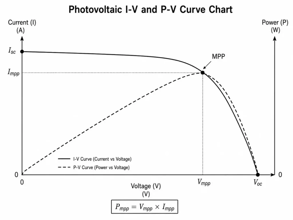
PV modules have non-linear I-V and P-V characteristics that change with solar irradiance, cell temperature, and operating conditions. Under a given operating condition, the PV array reaches a point where voltage (V) multiplied by current (I) produces the highest power output. This point is the Maximum Power Point (Pmpp).
Pmpp = Vmpp × Impp
Where:
- Pmpp = Maximum power output in Watts (W)
- Vmpp = Voltage at maximum power point in Volts (V)
- Impp = Current at maximum power point in Amperes (A)
Solar irradiance mainly changes PV output current, while cell temperature mainly changes operating voltage. According to the NREL PV Performance Model, module temperature increases cause V_mpp to drop significantly during hot summer conditions. In cold environments, Vmpp and Voc increase. Direct battery connections pull PV modules off peak voltage, killing daily yield.
1.2 DC-to-DC Converter Topologies in Off-Grid Inverters
Modern off-grid hybrid inverters place high-efficiency DC-to-DC MPPT charge controllers between the PV array and the internal DC bus. The MPPT controller monitors PV voltage and current, calculates power variation, and adjusts the Buck or Buck-Boost converter duty cycle to keep the PV array near its maximum power point.
In battery-based off-grid systems, the MPPT stage converts high PV string voltage (up to 500V DC) into the battery charging range while increasing output current accordingly. This voltage conversion directly shapes the modern off-grid solar power system architecture, allowing systems to utilize high-voltage PV strings efficiently. Higher PV string voltage reduces DC current, lowers I²R cable losses, and improves efficiency on longer cable runs.
Engineering Tip: For high-power hybrid inverters, select MPPT controllers with high tracking efficiency. This reduces conversion losses and thermal stress. Efficient DC-to-DC conversion maintains stable solar harvesting during high PV output periods.
2. Single MPPT Architecture: Circuit Topologies, Operational Limits, and Ideal Use Cases
2.1 Electrical Design of Single-Tracker Systems
A single MPPT architecture connects all PV strings to one Maximum Power Point Tracking engine. Inside the hybrid inverter, one control loop adjusts the operating point for the complete PV array.
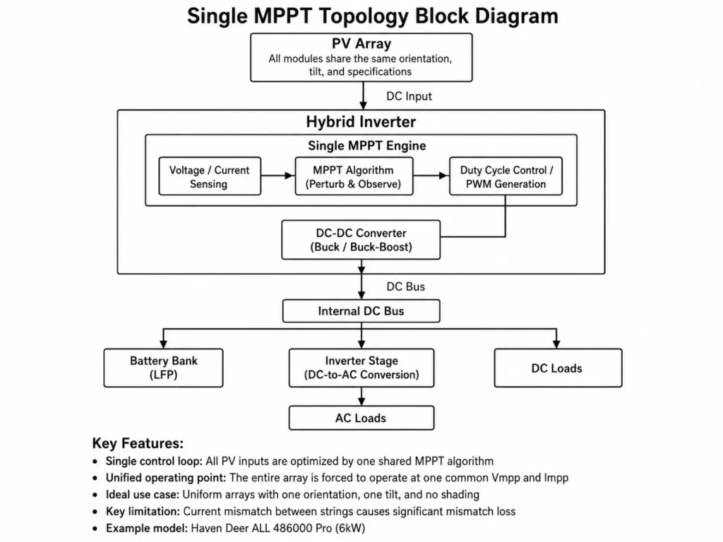
Single-tracker inverters like the Haven Deer ALL 486000 Pro demand strictly uniform PV arrays. The MPPT controller measures the combined voltage and current from the complete PV input. A single MPPT works best when all modules share the same tilt angle, azimuth, module specification, and solar exposure.
2.2 The Mismatch Penalty: Voltage and Current Bottlenecks in Single Strings
When non-uniform PV strings connect to a single MPPT tracker, mismatch losses reduce total system output. In a series string, all modules share the same current path. The module with the lowest current output limits the entire string current:
Istring = min(Imodule_1, Imodule_2, …, Imodule_n)
If East and West roof panels are combined into one string, or if strings contain different panel counts, the MPPT tracker may detect a distorted P-V curve with multiple local peaks. A single tracker cannot follow two optimum voltage points at the same time. It therefore operates at a compromise point and reduces total array output.
Common Engineering Mistake: Connecting unequal PV strings, such as one 6-panel string and one 8-panel string, to the same MPPT input. The voltage difference between strings can create reverse current flow. Higher-voltage strings back-feed shorter strings, tripping fault protection or frying modules.
Engineering Example: Single String Under Partial Shading
Consider an off-grid installation using eight 610W Grade A monocrystalline modules, each rated at Vmpp = 40.8V and Impp = 14.95A, wired in one series string to a 6kW single MPPT inverter.
- Unshaded Peak Array Power: 8 × 610W = 4,880W (326.4V DC × 14.95A).
- Shaded Scenario: A chimney shades two panels, reducing their irradiance by 50% and lowering their output current to 7.47A.
- Single MPPT Impact: The single MPPT forces the entire string current down to 7.47A to maintain series continuity.
- Actual Output Power: 326.4V DC × 7.47A = 2,438.2W.
- System Power Loss: Total array output drops by about 50%, even though 75% of the modules still receive full sunlight.
3. Dual Independent MPPT Architecture: Electrical Isolation, Multi-Array Handling, and Shading Resilience
3.1 Dual Independent Bus Architecture
A dual independent MPPT architecture uses two independent DC-to-DC converter stages inside one hybrid inverter. Each MPPT channel has its own control loop, voltage and current sensing circuits, and tracking algorithm.
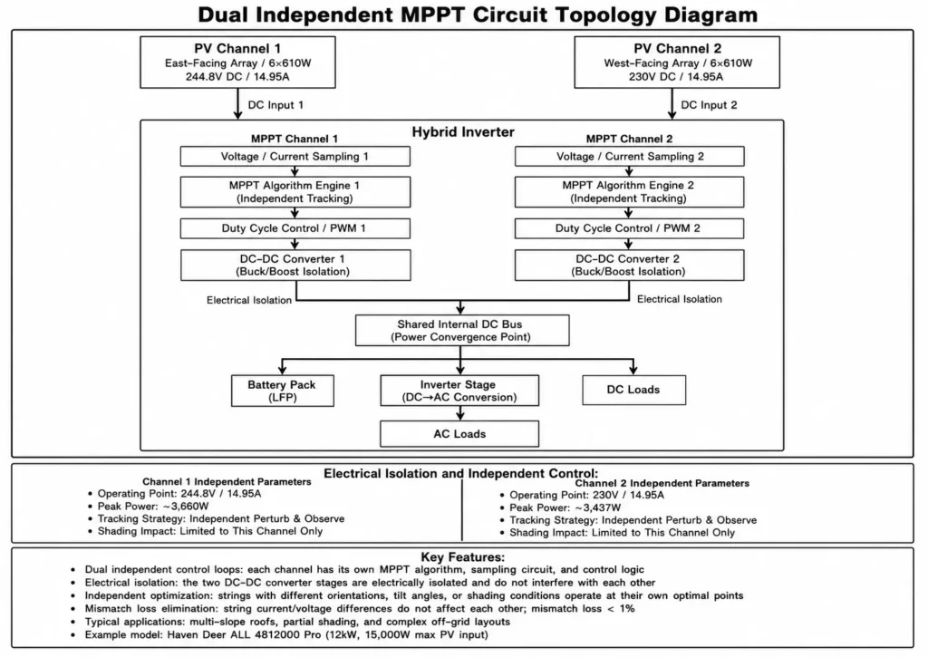
In off-grid hybrid solar inverters such as the Haven Deer ALL 4812000 Pro (12kW output, 15,000W max PV input, 60–500V DC MPPT range, 27A × 2 input current), both MPPT channels operate independently. Channel 1 can process a high-voltage 400V DC PV string at 14A, while Channel 2 can simultaneously process a 220V DC PV string at 20A. Each conversion channel processes its PV input and delivers power to the shared internal DC bus. The inverter achieves up to 99% peak PV-to-inverter efficiency.
3.2 Mitigation of Orientation Mismatch and Partial Shading
Dual independent MPPT controllers solve common installation issues caused by different PV orientations, tilt angles, and shading conditions:
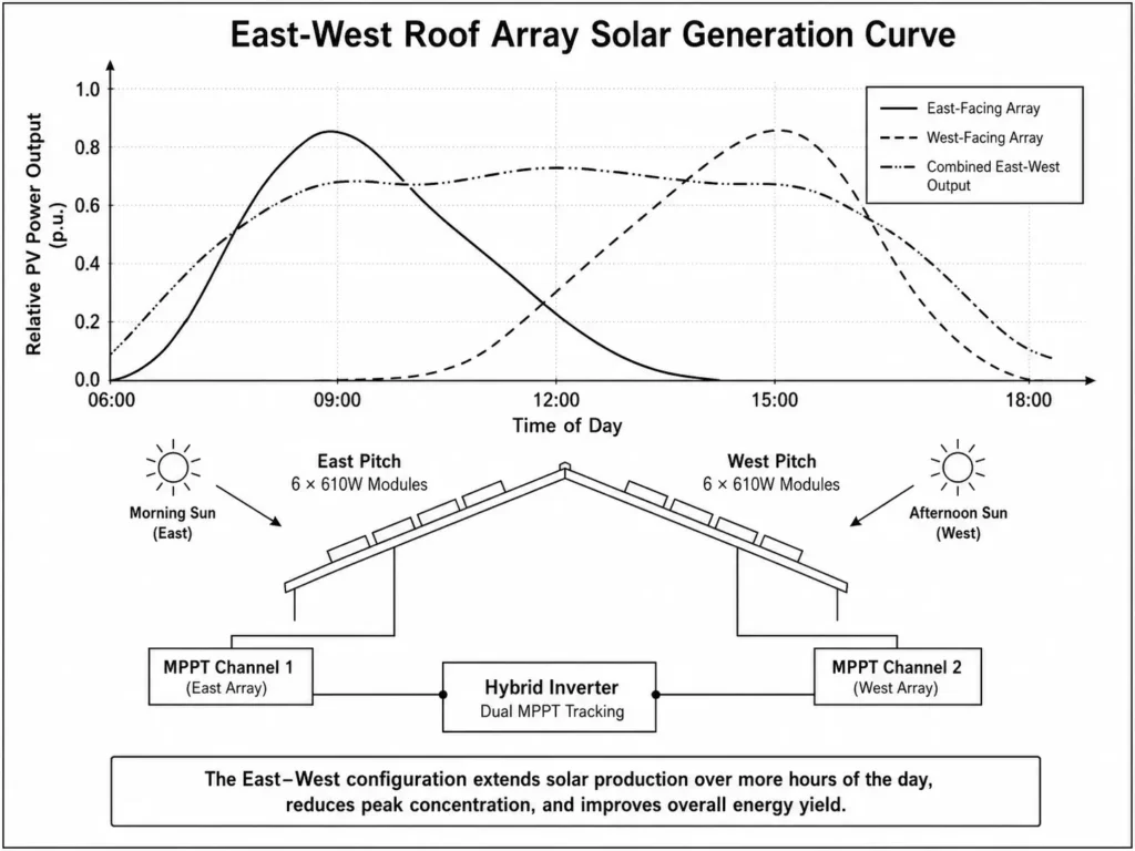
- Multi-Aspect Roof Layouts: Splitting PV arrays across East and West roof pitches allows each MPPT channel to optimize its own PV generation profile. The East array can capture morning production, while the West array continues harvesting afternoon energy without affecting the other channel.
- Tilt Angle Variance: PV arrays installed at different tilt angles can operate at different Vmpp values. Separate MPPT channels allow each array to maintain independent tracking performance.
- Partial Shading Isolation: Shadows from trees, communication towers, or nearby buildings mainly affect the PV string connected to that MPPT channel. The second channel can continue operating independently when its PV array receives sufficient sunlight.
Practical Engineering Recommendation: Select a dual independent MPPT hybrid inverter when PV arrays use different roof pitches, azimuth orientations, or have predictable shading conditions.
Engineering Example: East-West Split Array Yield Analysis
An installer configures twelve 610W modules on a residential villa. Six panels face East (1,830W total nameplate capacity) and six panels face West (1,830W total nameplate capacity).
- Channel 1 (East String – Morning Peak): Operates at 244.8V DC and 14.95A, supplying 3,660W peak morning power to the internal DC bus.
- Channel 2 (West String – Morning Diffuse Light): Receives indirect sunlight and operates independently at 230V DC and 3.2A, adding 736W to the DC bus.
- Combined System Output: 3,660W + 736W = 4,396W.
- Single MPPT Contrast: Paralleling these strings on one MPPT triggers current mismatch, cutting morning output by 50%.
4. Electrical Engineering Comparison: Single vs. Dual MPPT Trackers
Choosing between single and dual MPPT topologies impacts PV layout flexibility, overall energy yield, and the high-voltage MPPT benefits for cable sizing.
Table 1: Technical & Topographical Comparison Matrix
| Electrical / Mechanical Parameter | Single MPPT Architecture (e.g., Haven Deer ALL 486000 Pro) | Dual Independent MPPT Configuration (e.g., Haven Deer ALL 4812000 Pro) |
|---|---|---|
| Independent Tracking Channels | 1 Channel | 2 Channels (Electrically Isolated) |
| MPPT Operating Voltage Range | 120–500V DC | 60–500V DC |
| Max PV Input Capacity | 9,000W total | 15,000W total (7,500W × 2 typical configuration, up to 9,000W on a single channel) |
| Max PV Input Current | 27A | 27A × 2 (54A combined input capacity) |
| Peak PV Conversion Efficiency | >94% | Up to 99% |
| Multi-Aspect Roof Suitability | Limited (Requires uniform orientation and tilt) | Suitable (Handles East/West and split tilts independently) |
| Shading Mismatch Vulnerability | Higher (Shading can reduce the current of the complete string) | Lower (Shading impact is limited to the affected MPPT channel) |
| Balance of System (BOS) Complexity | Low (Single DC cable pair into inverter) | Medium (Dual DC cable pairs into combiner/inverter) |
| Target Application Fit | Single-pitch roofs, uniform PV arrays, basic residential applications | Multi-pitch homes, commercial sites, and off-grid systems with complex PV layouts |
Table 2: Simulated Annual Yield Mismatch Penalty (East-West Roof Setup)
| Installed Wiring Topology | Physical Array Layout | Expected Mismatch Energy Loss | Operational Risk Profile |
|---|---|---|---|
| Single MPPT (Paralleled Strings) | 6 Panels East + 6 Panels West on 1 MPPT | 18%–25% Annual Yield Loss | Higher (Potential inter-string current imbalance) |
| Single MPPT (Series String) | 3 Panels East + 3 Panels West in 1 String | 30%–42% Annual Yield Loss | High (Significant current mismatch and output reduction) |
| Dual Independent MPPT | 6 Panels East (MPPT 1) + 6 Panels West (MPPT 2) | <1% Mismatch Loss | Low (Independent DC conversion paths) |
5. Mathematical Modeling & Energy Yield Sizing Calculations
5.1 Cold-Weather Maximum Open-Circuit Voltage (Voc) Equation
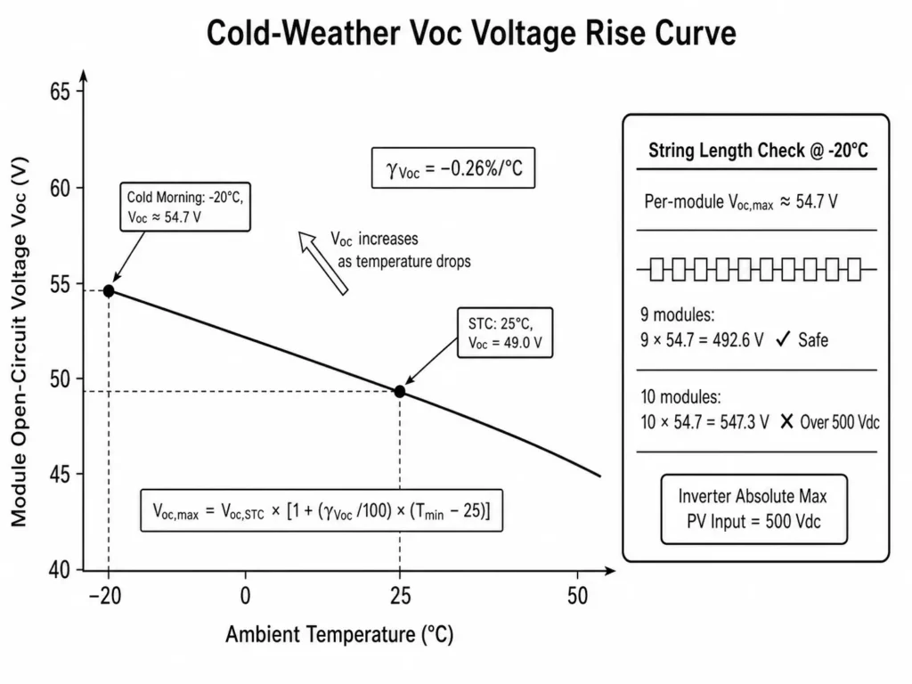
Selecting PV string length relies on calculating cold-weather open-circuit voltage safety margins to prevent low-temperature over-voltage tripping. PV module voltage rises as ambient temperature drops below Standard Test Conditions (STC = 25°C). Exceeding the inverter’s maximum PV input voltage, such as the 500V DC limit on Haven Deer hybrid inverters, can trigger over-voltage protection and damage the PV input stage.
Calculate the maximum PV string open-circuit voltage (Voc,max) at the lowest expected site temperature (Tmin) using the standard thermal correction methodology outlined in the Sandia PVPMC Modeling Guide:
Voc,max = Voc,STC × [1 + (γVoc / 100) × (Tmin – 25)]
Where:
- Voc,max = Maximum predicted open-circuit voltage per module at the minimum site temperature (V)
- Voc,STC = Rated open-circuit voltage per module at STC (25°C) (V)
- γVoc = Temperature coefficient of Voc (%/°C, expressed as a negative number)
- Tmin = Lowest historical ambient temperature recorded at the project site (°C)
5.2 String Mismatch Loss Formula & Worked Sample Sizing
Estimate mismatch losses for non-uniform PV modules connected in one series string using the following current constraint equation:
Ploss,mismatch = Σ Pmpp,k – [min(Impp,1..n) × Σ Vmpp,k]
Worked Step-by-Step Field Calculation
An engineering contractor designs an off-grid installation in Central/Eastern Europe, where winter temperatures can drop to -20°C. The project uses Haven Deer 610W Grade A monocrystalline solar panels.
- Module Nameplate Specifications (STC):
- Nominal Power (Pmax): 610W
- Open-Circuit Voltage (Voc,STC): 49.0V
- Voltage at MPP (Vmpp,STC): 40.8V
- Current at MPP (Impp,STC): 14.95A
- Temperature Coefficient (γVoc): -0.26%/°C
- Inverter Voltage Limits: MPPT range 60–500V DC; maximum PV open-circuit voltage limit is 500V DC.
- Environmental Limit: Tmin = -20°C.
Step 1: Calculate Maximum Voltage Per Module at -20°C
Voc,max = 49.0 × [1 + (-0.26 / 100) × (-20 – 25)]
Voc,max = 49.0 × [1 + (-0.0026) × (-45)]
Voc,max = 49.0 × 1.117 = 54.733V DC
Step 2: Determine Maximum Safe Series String Length
To keep PV string voltage below the inverter’s 500V DC input limit during cold winter mornings:
Max Modules per String = Floor(Max Inverter Voc / Voc,max)
= Floor(500V DC / 54.733V DC)
= Floor(9.13) = 9 modules
- Verification: 9 modules × 54.733V DC = 492.6V DC total array Voc,max.
- Safety Margin Result: 492.6V DC remains below the 500V DC absolute limit. Connecting 10 panels in series increases winter Voc,max to 547.3V DC, exceeding the inverter input rating and damaging the MPPT stage.
6. Array Design & String Configuration Strategies for Complex Roofs & Extreme Climates
6.1 Dual Aspect (East-West) Array Sizing Strategy
Designing off-grid PV arrays in regions with strong seasonal solar variation, such as Eastern Europe, requires matching array layout with daily solar production patterns. High-pitch East-West roof structures benefit from dual independent MPPT channels because each roof section can operate separately.
+-----------------------------------------------------------------------------------+
| DUAL-PITCH EAST/WEST PV ARRAY & MPPT TRACKING TOPOLOGY                            |
+-----------------------------------------------------------------------------------+
|                                                                                   |
|        [Sun - 09:00 AM]                                [Sun - 04:00 PM]           |
|              \                                                /                   |
|               \                                              /                    |
|                ▼                                            ▼                     |
|       /─────────────────\                         /─────────────────\             |
|      /    East Pitch     \                       /    West Pitch     \            |
|     /  6 x 610W Modules   \                     /  6 x 610W Modules   \           |
|    /                       \                   /                       \          |
|   /─────────────────────────\                 /─────────────────────────\         |
|               │                                           │                       |
|               ▼                                           ▼                       |
|   [Inverter MPPT Channel 1]                   [Inverter MPPT Channel 2]           |
|                                                                                   |
+-----------------------------------------------------------------------------------+
By distributing balanced PV strings between Channel 1 and Channel 2 on a dual MPPT inverter, such as the ALL 4812000 Pro, the system extends daily solar production periods across different sun angles. This reduces short-duration PV peaks and maintains longer battery charging periods during variable winter conditions.
6.2 High-Power Module Integration (610W+ Grade A Modules)
High-output monocrystalline modules (550W–620W) pull over 14A to 15A during peak operation.
- Current Input Capacity: Ensure the inverter MPPT channels support the PV module operating current. The Haven Deer ALL 486000 Pro (27A single channel) and ALL 4812000 Pro (27A × 2 dual channels) are compatible with 610W Grade A modules within their specified input limits.
- Minimum Summer Operating Voltage: During high summer temperatures (+40°C), PV module operating voltage decreases:
Vmpp,summer = Vmpp,STC × [1 + (γVmp / 100) × (Tcell – 25)]
String design must keep summer operating voltage above the inverter’s minimum MPPT voltage (60V DC for ALL 4812000 Pro and 120V DC for ALL 486000 Pro) to maintain MPPT tracking during hot conditions.
A practical note: Depending on the choice of single-string vs. multi-string wiring to dual MPPT inverters, an IP65 PV Combiner Box may be required between the PV array and the hybrid inverter. Using 500V DC surge protection devices (SPD 2P 20–40kA), 63A 2P DC circuit breakers, and 32A DC fuses per string provides additional protection against surge events and overcurrent conditions.
7. Off-Grid System Integration: Matching MPPT Inverters with Grade A LFP Storage & Generators
7.1 Coordinating MPPT Output with BMS & EMS Control Hierarchy
The system relies on an integrated EMS to coordinate PV, battery, and generator power flows within the hybrid inverter architecture. MPPT controllers are not standalone chargers; the EMS manages charging strategies and coordinates operation with the BMS.
+-----------------------------------------------------------------------------------+
| HYBRID INVERTER & BATTERY MANAGEMENT TOPOLOGY                                     |
+-----------------------------------------------------------------------------------+
|                                                                                   |
|  [PV Arrays (MPPT 1 & 2)] ──► [Hybrid Inverter Energy Hub] ◄──► [Master LFP BMS]  |
|                                             │    (CAN / RS485 Bus)      │         |
|                                             ▼                           ▼         |
|                                      [Main AC Loads]       [Grade A LiFePO₄ Cells]|
|                                                                                   |
+-----------------------------------------------------------------------------------+
Haven Deer off-grid solar power systems use Grade A Lithium Iron Phosphate (LiFePO₄) battery modules, including the AL-WM512200 (10.24kWh Wall-Mounted Home Solar Battery) and MB512300 (15.0kWh Floor-Standing Mobile Cabinet Off-Grid Solar Battery). The BMS monitors individual cell voltage, battery temperature, and SOC. Closed-loop CAN/RS485 communication enables the Master BMS to exchange operating data with the inverter EMS.
When the battery approaches full charge or cell temperature drops below 0°C, the BMS sends updated charge limits to the EMS. The EMS adjusts MPPT charging by reducing charge current or limiting PV power according to BMS commands. During charging, the system transitions from Constant Current (CC) to Constant Voltage (CV) control to maintain LiFePO₄ charging safety.
7.2 Automated Generator Integration via Dry Contact Control
During extended periods of low solar irradiance, such as heavy winter cloud conditions, PV generation may not fully meet daily load demand. Automated generator integration provides backup power when battery reserves approach configured limits.
                             [PV Input (Low Irradiance)]
                                          │
                                          ▼
[Battery Pack (SOC Drops to 20%)] ──► [Hybrid Inverter EMS] ──(Dry Contact Signal)──► [AC Generator Auto-Start]
                                          │                                           │
                                          ▼                                           ▼
                                  [Shed Smart Load]                         [AC Charge Battery / Supply Loads]
- Triggering Mechanics: Dropping below 20% SoC triggers the EMS dry contact.
- Auto-Start Execution: The dry contact signal triggers the generator controller or automatic transfer system to start the auxiliary generator.
- Power Routing: The generator supplies AC power through the inverter AC input. The inverter can support connected loads through the Main Output while using the internal charger to recharge the LiFePO₄ battery bank.
- Automated Shutdown: When solar production recovers or battery SOC reaches the configured upper limit, the EMS opens the dry contact relay and stops the generator through the controller.
8. Common Engineering Mistakes and Design Pitfalls in MPPT Selection
Many off-grid PV issues come from incorrect array sizing, string configuration, or wiring design. Check the following four items during system specification:
- Exceeding Cold-Weather Maximum Voc: Ignoring winter temperature correction causes high-voltage array trips. Cold winter mornings can push PV voltage above the inverter’s 500V DC limit, triggering over-voltage protection and damaging the MPPT input stage.
- Connecting Strings with Unequal Panel Counts to One MPPT: Connecting a 6-panel string and an 8-panel string to the same MPPT channel creates voltage mismatch between strings. This may result in reverse current, additional losses, and increased thermal stress on PV components.
- Operating Below Minimum MPPT Voltage in Summer Heat: Strings that are too short, such as two 40V modules producing approximately 80V DC at STC, may fall below the inverter’s minimum MPPT operating voltage. High module temperatures further reduce voltage and can cause the MPPT controller to stop tracking during peak solar hours.
- Ignoring Maximum PV Input Current Limits: Connecting three 610W PV strings in parallel (14.95A × 3 = 44.85A) to a single MPPT channel rated for 27A exceeds the input current specification. The inverter may limit input current and reduce usable PV power.
Learn more about Common Installation Mistakes Damaging Off-Grid Inverters.
4-Point MPPT String Sizing Verification Checklist
- Check 1 (Voc,max Limit): Is the array Voc,max at local Tmin below the inverter’s 500V DC maximum input limit? (Recommended design target: 450–470V DC.)
- Check 2 (Vmpp,min Limit): Is the array Vmpp at local Tmax (+40°C to +50°C) above the inverter’s minimum MPPT operating voltage (60V DC / 120V DC)?
- Check 3 (Ipv,max Limit): Does the PV operating current remain within the rated input current of each MPPT channel (27A per channel)?
- Check 4 (Orientation Isolation): Are PV strings with different orientations or tilt angles connected to separate MPPT channels?
9. Engineering Selection Framework & Actionable Procurement Guidelines
Select the appropriate MPPT topology using the following framework based on PV layout, site conditions, and system power requirements:
+-----------------------------------------------------------------------------------+
| OFF-GRID SOLAR ESS INVERTER SELECTION FLOWCHART                                   |
+-----------------------------------------------------------------------------------+
|                                                                                   |
|                         [Off-Grid Solar ESS Project Site]                         |
|                                         │                                         |
|                             Is the PV Array Uniform?                              |
|               (Same orientation, tilt angle, and minimal shading?)                |
|                                         │                                         |
|                      ┌──────────────────┴──────────────────┐                      |
|                      │ YES                              NO │                      |
|                      ▼                                     ▼                      |
|     ┌──────────────────────────────────┐  ┌──────────────────────────────────┐    |
|     │   Single MPPT Configuration      │  │  Dual Independent MPPT Config    │    |
|     │ • Model: ALL 486000 Pro (6kW)    │  │ • Model: ALL 4812000 Pro (12kW)  │    |
|     │ • PV Input: Up to 9,000W         │  │ • PV Input: Up to 15,000W        │    |
|     │ • Array: Single Orientation /    │  │ • Array: East-West /             │    |
|     │   Uniform Pitch                  │  │   Multiple Tilts                 │    |
|     └──────────────────────────────────┘  └──────────────────────────────────┘    |
|                                                                                   |
+-----------------------------------------------------------------------------------+
Direct Selection Guide
- Select a Single MPPT Architecture (e.g., Haven Deer ALL 486000 Pro) when:
- The PV array is installed on a single roof orientation or a uniform ground-mounted structure with consistent solar exposure.
- The total PV nameplate capacity is ≤ 9,000W.
- Simple wiring and lower balance-of-system complexity are required project conditions.
- Select a Dual Independent MPPT Architecture (e.g., Haven Deer ALL 4812000 Pro) when:
- The PV array is distributed across East-West roof sections or multiple tilt angles.
- Nearby obstacles create predictable partial shading on part of the PV array.
- Total PV nameplate capacity ranges from 9,000W to 15,000W.
- Extended daily solar production and high PV conversion efficiency are required for the project.
For other system sizing questions, see our Step-by-Step Engineering Guide to Sizing Off-Grid ESS Kits.
10. Frequently Asked Questions (Technical & System Design)
Q1: What is the primary technical advantage of a dual MPPT inverter in an off-grid system?
A dual MPPT inverter uses two independent DC tracking channels. Separate PV strings with different orientations, tilt angles, or shading conditions can operate at their own Maximum Power Points, reducing mismatch losses.
Q2: Can I connect panels with different wattage ratings to a dual MPPT inverter?
Yes. Each MPPT channel operates independently, so different PV module types can connect to Channel 1 and Channel 2 as long as each PV string remains within its voltage and current limits.
Q3: What happens if a PV array’s open-circuit voltage exceeds the 500V DC limit?
Exceeding the 500V DC Voc limit can trigger internal over-voltage protection and damage DC input components. Always calculate temperature-corrected Voc,max based on the lowest expected site temperature.
Q4: Is a dual MPPT inverter necessary for a flat, unshaded rooftop?
Not necessarily. If all PV modules share the same orientation, tilt angle, module specifications, and solar exposure, a single MPPT inverter, such as the Haven Deer ALL 486000 Pro, provides suitable performance with a simpler configuration.
Q5: How does partial shading impact a single MPPT string vs. a dual MPPT system?
In a single MPPT string, shading on one module reduces the operating current of the entire series string. In a dual MPPT system, shading on one PV string mainly affects its connected MPPT channel, while the other channel can continue operating independently.
Q6: What is the minimum operating MPPT voltage for Haven Deer hybrid inverters?
The ALL 486000 Pro operates with an MPPT voltage range of 120–500V DC (recommended operating range: 300–400V DC). The ALL 4812000 Pro provides a wider 60–500V DC MPPT range, allowing greater flexibility when designing shorter PV strings.
Q7: How does high ambient summer temperature affect MPPT string voltage design?
High temperatures reduce PV operating voltage (Vmpp). PV string design must keep Vmpp above the inverter’s minimum MPPT voltage during maximum summer temperatures.
Q8: Can I combine two MPPT channels into a single massive PV string?
No. A single PV series string should not be connected across two MPPT inputs. Two independent PV strings can be connected to separate MPPT channels as long as each string meets the voltage and current requirements of its channel.
Q9: Why is peak DC-to-DC efficiency higher on the ALL 4812000 Pro (99%) compared to standard inverters?
The ALL 4812000 Pro uses a dual MPPT conversion architecture designed to improve power handling efficiency and thermal management during PV energy conversion.
Q10: How does the MPPT charge controller interact with the LiFePO₄ Battery Management System (BMS)?
The inverter’s Energy Management System (EMS) communicates with the BMS through closed-loop CAN/RS485 protocols. When the battery reaches full charge or detects low-temperature charging conditions below 0°C, the BMS sends charge limit commands to the EMS to adjust MPPT charging current.
Q11: What sizing safety margin should be applied for cold winter climates in Eastern Europe?
Calculate the lowest historical site temperature (Tmin, such as -20°C). Apply the PV module temperature coefficient (γVoc) to ensure total string Voc,max remains below the inverter limit. A design target of 450–470V DC provides additional voltage margin below the 500V DC absolute limit.
Q12: Does a dual MPPT inverter increase daily generator fuel consumption in an off-grid system?
No. By improving solar energy capture under different PV orientations and shading conditions, dual MPPT can maintain higher battery SOC and reduce generator operating frequency.
11. Request an Engineering Design Review & Custom Off-Grid ESS Sizing Plan
Designing off-grid solar energy systems for complex PV layouts or extreme cold climates requires detailed electrical calculations. Professional string sizing identifies potential mismatch losses and PV over-voltage risks before installation.
Contact Haven Deer’s engineering team for PV string calculation review, single-line diagram evaluation, and a customized Off-Grid ESS Kit proposal based on applicable IEC requirements.