Quick Summary: To set up remote monitoring on the Solar of Things App, connect a compatible Wi-Fi module or 4G DTU device to the hybrid inverter’s communication port. Technicians configure the device using 2.4 GHz Wi-Fi AP mode or 4G cellular provisioning, then register the inverter on the platform. This grants direct access to EMS and BMS telemetry.
1. Telemetry System Architecture: WiFi Module vs. 4G DTU
Modern off-grid solar energy storage systems (BESS) use telemetry to monitor operating status and coordinate PV, battery, grid, and generator assets. Haven Deer ALL 486000 Pro and ALL 4812000 Pro hybrid inverters serve as central energy hubs, aggregating data from the control unit and closed-loop CAN/RS485 BMS. Compatible Wi-Fi or 4G telemetry modules transmit this data to the Solar of Things cloud platform.
1.1 Local Physical Protocols: RS232/RS485 & Modbus RTU Frame Structure
At the physical layer, the inverter communicates with telemetry hardware over an RS232 or RS485 serial interface. The underlying protocol is industrial Modbus RTU. The inverter acts as a Modbus server, while the telemetry module polls and exchanges data according to serial settings.
The Modbus RTU telemetry frame consists of:
- Device Address (1 Byte): Identifies the target inverter in single or parallel configurations.
- Function Code (1 Byte): Defines read and write operations for register management.
- Data Payload (N Bytes): Carries metrics like PV voltage, grid frequency, AC output power, battery SoC, and BMS temperature data.
- CRC Checksum (2 Bytes): Prevents data corruption over serial transmission lines.
1.2 Cloud Ingestion Layer: MQTT & Cellular Network Topologies
Once the module receives serial Modbus RTU data, it packages the payload for cloud transmission to the Solar of Things platform.
- Wi-Fi Transport: Connects to local 2.4 GHz IEEE 802.11 b/g/n routers. It delivers low-latency telemetry (100–500 ms) for residential and commercial sites.
- 4G Cellular Transport: Bypasses local networks using a 4G DTU module over cellular bands. This topology suits remote agricultural sites, island microgrids, and telecom outposts.
| Specification / Parameter | WiFi Telemetry Module | 4G DTU Cellular Module |
| Primary Deployment Site | Residential / Commercial with existing Wi-Fi | Remote off-grid, agricultural, telecom outposts |
| Physical Interface | DB9 / RS232 / RS485 Aviation Plug | DB9 / RS232 / RS485 Aviation Plug |
| Wireless Protocol | IEEE 802.11 b/g/n (2.4 GHz) | LTE Cellular Network |
| Local Infrastructure Required | Local Wi-Fi Router with Internet access | Cellular Network Coverage (SIM Card) |
| Power Consumption | < 1.5 W | < 3.0 W peak during transmission |
| Data Latency | 100–500 ms | 500–2000 ms |
| Operating Temperature | -20°C to +65°C | -30°C to +75°C |
| Cost Profile | Lower hardware cost; requires existing internet access | Higher hardware cost; requires cellular SIM data plan |
Engineering Tip: When daisy-chaining multiple inverters over RS485, install a 120 Ω termination resistor on the final device. This suppresses signal reflection and stabilizes communication.
2. Hardware Installation & Interface Wiring Protocol
Install the telemetry module before system commissioning to establish stable serial communication. Haven Deer hybrid inverters feature external communication ports, allowing module installation without opening the IP21 enclosure.
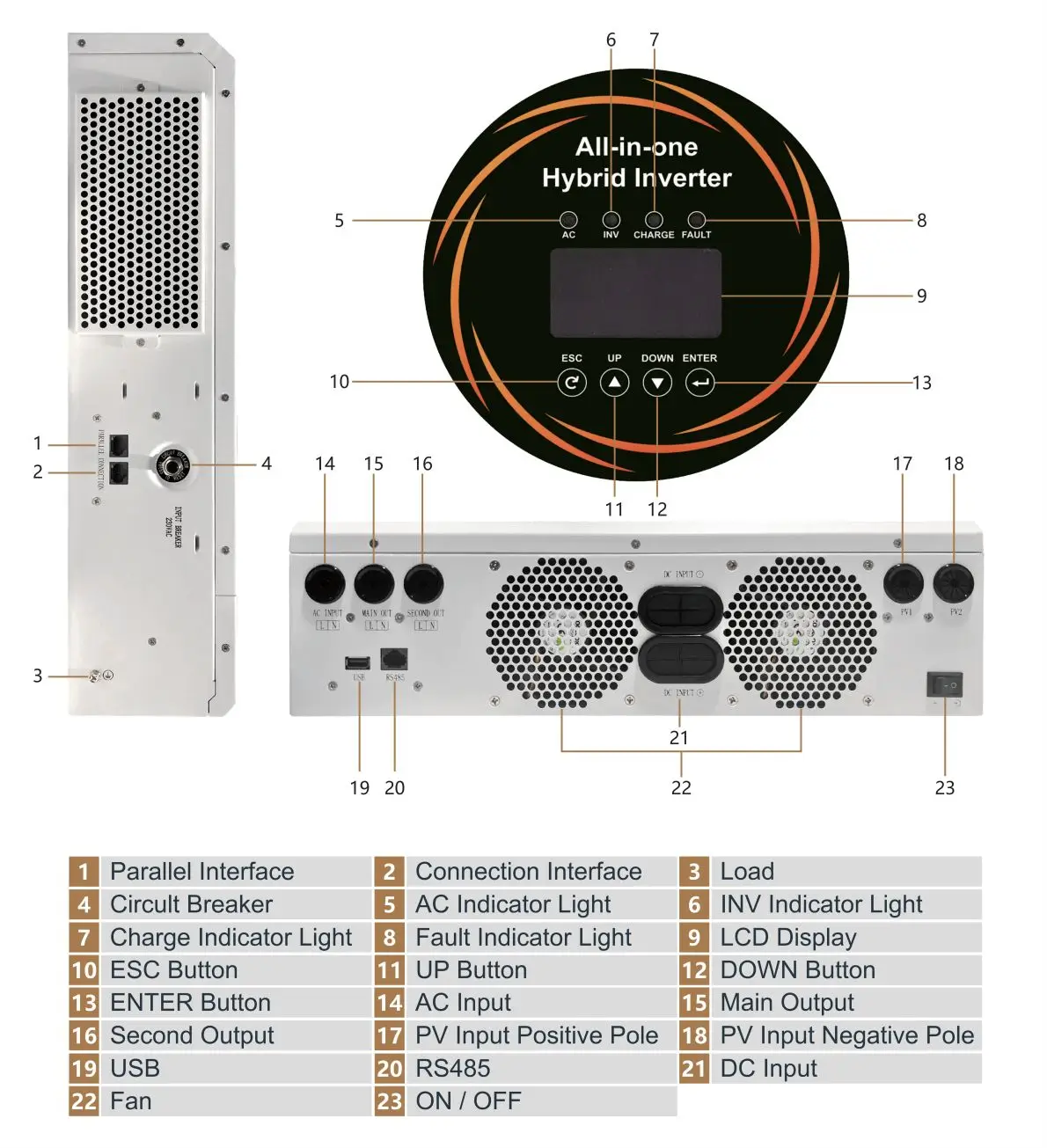
2.1 Attaching the Telemetry Dongle to ALL 486000 / 4812000 Pro Models
- Power Isolation: Open the AC input breaker, PV DC isolator, and battery breaker. Confirm the LCD screen is completely dark.
- Port Identification: Locate the dedicated communication port on the bottom connection panel.
- Mechanical Coupling: Align the connector, press firmly until seated, and hand-tighten the captive screws. If using aviation connectors, rotate the locking collar clockwise until fully latched.
- Antenna Positioning: Connect external antennas to 4G DTU modules. Position the antenna vertically, keeping it clear of metal conduits or structural steel to prevent RF attenuation.
2.2 LED Status Indicator Matrix & Power-On Diagnostics
Re-energize the battery circuit breaker to power up the inverter control unit. The communication port feeds auxiliary power directly to the telemetry module. Check the diagnostic LEDs to verify hardware status:
| LED Label | Color | Status State | System Operational Meaning |
|---|---|---|---|
| PWR (Power) | Solid Red | On | Auxiliary power supply confirmed; telemetry module controller powered up. |
| NET (Network) | Flashing Green | Slow Flash (1 Hz) | Searching for local Wi-Fi AP or registering on 4G LTE network. |
| NET (Network) | Solid Green | On | Successfully connected to the configured network and cloud monitoring platform. |
| COM (Comm) | Flashing Yellow | Rapid Flash | Active Modbus RTU data exchange occurring between inverter and module. |
| COM (Comm) | Off | Off | No serial communication. Verify port connection and communication settings. |
Common Mistake: Over-tightening communication connectors damages internal header pins. Hand-tighten all connections without tools.
3. Step-by-Step Provisioning via Solar of Things App
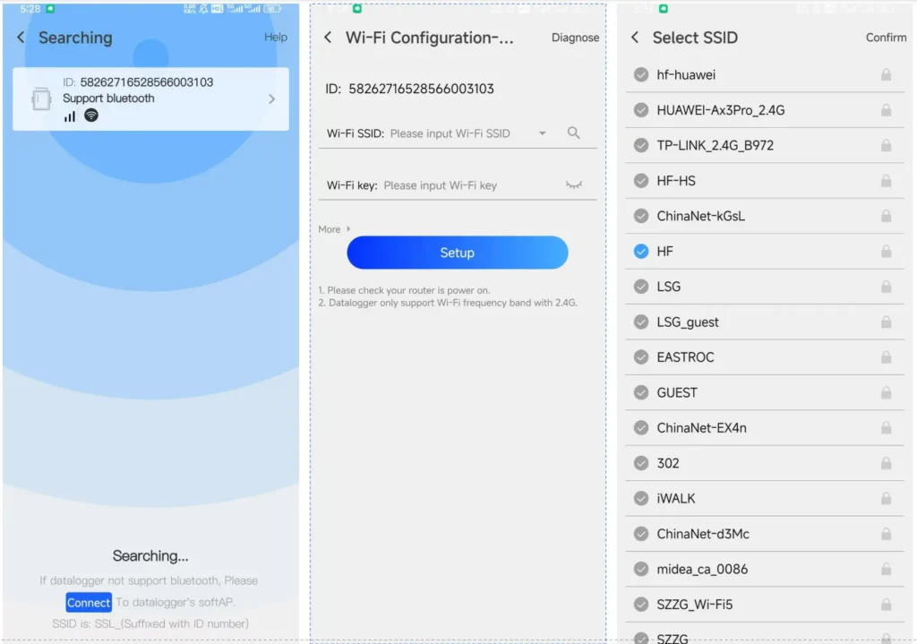
Once status LEDs confirm startup, complete device registration and cloud pairing via the Solar of Things App on iOS or Android.
| Feature / Capability | Direct AP Mode (Local Wireless) | Cloud Telemetry Mode (Solar of Things Cloud) |
| Connection Range | 10–15 meters from inverter | Global access via internet |
| Internet Requirement | None (Direct point-to-point) | Active Wi-Fi or 4G data link at site |
| Data History Logging | Real-time local monitoring (no long-term storage) | Cloud trend logging and analytics |
| Use Case | On-site commissioning and emergency setup | Fleet management, remote support, client monitoring |
| Remote Parameter Writing | Supported via local access | Supported remotely with installer authorization |
3.1 Account Registration & Plant Hierarchy Creation
- Download and launch the Solar of Things App from the App Store or Google Play.
- Select Register Installer Account, enter a business email, and complete account verification.
- Tap Create New Plant, enter the site name, select the local time zone, and input location data.
3.2 WiFi Module Pairing Protocol (2.4 GHz Network Handshake)
- Disable Mobile Data: Turn off cellular data on the mobile device to prevent disconnects from the telemetry module AP during provisioning.
- Activate Provisioning Mode: Hold the Wi-Fi module Reset button until the NET LED flashes rapidly.
- Connect to Module AP: Open mobile Wi-Fi settings and connect to the module’s broadcast SSID.
- Network Configuration: Return to the app, tap Add Device, and enter network configuration.
- Credentials Configuration: Select the client’s 2.4 GHz Wi-Fi SSID, enter the password, and initiate pairing. The module saves credentials and registers with the cloud platform.
3.3 4G DTU Cellular Provisioning & APN Configuration
- Insert an active micro-SIM card into the 4G DTU before powering up.
- In the app, tap Scan QR Code and scan the barcode on the 4G DTU.
- If using private cellular networks, open Advanced Settings, enter the carrier APN credentials, and save.
+-----------------------------------------------------------------------------------+
| PROVISIONING CHECKLIST FOR INSTALLERS                                             |
+-----------------------------------------------------------------------------------+
| [ ] 1. Telemetry module power supply verified through the PWR LED status.         |
|                                                                                   |
| [ ] 2. Client router broadcast verified on 2.4 GHz band (5 GHz networks isolated). |
|                                                                                   |
| [ ] 3. Telemetry module serial number successfully registered to the correct       |
|        plant account.                                                             |
|                                                                                   |
| [ ] 4. Mobile device cellular data turned OFF during AP-mode Wi-Fi provisioning.   |
|                                                                                   |
| [ ] 5. Communication status verified through the COM LED data exchange indication. |
+-----------------------------------------------------------------------------------+
For more checks, refer to the Commissioning Checklist for Installers During First-Time Setup.
4. Remote Parameter Tuning & EMS Operating Strategy
Cloud telemetry allows engineers to tune EMS parameters remotely, eliminating routine truck rolls.
4.1 Switching Energy Priority Modes (SBU / SUB / SUF / ToU)
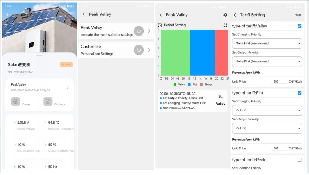
Installers reconfigure inverter operating modes via the app based on solar availability, load profiles, or grid tariffs:
- SBU Mode (Solar -> Battery -> Utility): Prioritizes PV for load supply and battery charging. If PV drops, the battery supplies loads until reaching the cutoff threshold. Grid acts as tertiary backup.
- SUB Mode (Solar -> Utility -> Battery): Directs PV power to loads first. If generation falls short, utility grid power covers the deficit, reserving battery energy for outages.
- ToU Mode (Time-of-Use): Schedules charge and discharge windows around utility tariff structures. Charge during off-peak rates; discharge during peak pricing.
4.2 Setting Remote SOC/Voltage Thresholds & Dry Contact Triggers
App settings let installers configure dry contact relay thresholds to automate generator start and stop cycles.
- Generator Start Threshold: Set via battery SoC % (in closed-loop CAN mode) or DC bus voltage.
- Generator Stop Threshold: Set to open the relay once the battery reaches target SoC and bulk charging completes.
| Parameter Name | Remote Adjustment Range | Default Setting | Recommended Engineering Boundary |
| Energy Operating Mode | SBU / SUB / SUF / ToU | SBU | Match to regional grid stability requirements |
| Max Combined Charging Current | 10A to 160A (ALL 4812000 Pro) | 60A | Configure according to battery BMS charging current limits and total parallel battery capacity |
| Battery Low DC Cutoff Voltage | 40.0V DC to 48.0V DC | 42.0V DC | Configure according to battery chemistry, BMS protection limits, and operating requirements |
| Dry Contact Auto-Start SOC | 10% to 50% SOC | 20% SOC | Set to 20% SOC (or 48.0V DC) for emergency auto-start |
| Dry Contact Auto-Stop SOC | 60% to 100% SOC | 85% SOC | Set to 80%–85% SOC to prevent unnecessary generator runtime |
Practical Engineering Example:
An off-grid farm in Central Asia pairs an ALL 4812000 Pro inverter with two MB512300 floor-standing battery cabinets (30.0 kWh total). In winter, low irradiance causes daily solar generation to drop below base load demand.
The engineer configures dry contact auto-start thresholds remotely:
- Engage Threshold: Set to 20% SoC (~48.0V DC). At 20% SoC, the inverter closes the dry contact relay to auto-start the generator.
- Disengage Threshold: Set to 80% SoC (~54.4V DC). At 80% SoC, the relay opens and shuts down the generator. This minimizes fuel consumption while preserving battery health.
Common Mistake: Setting charge voltage above the BMS limit (58.4V DC for 16S LiFePO4) triggers over-voltage protection. This drops inverter-BMS communication.
5. Diagnostic Data Logging, Graphing & Firmware Management
A widening cell voltage delta during high-current draw signals cell imbalance. Early detection lets technicians intervene before trips occur.
5.1 Polling Frequencies & BMS Cell Voltage Curve Monitoring
The Solar of Things cloud platform logs telemetry data at configurable 5- to 60-second intervals. In closed-loop CAN/RS485 mode with Haven Deer Grade A LiFePO4 batteries, the app monitors key BMS telemetry:
- Individual 16S Cell Voltages: Tracks delta between the highest and lowest cells.
- Temperature Sensor Logs: Tracks MOSFET, ambient, and cell temperatures.
- Health Metrics: Displays battery SoH and cumulative cycle counts.
A widening cell delta during high-current draw signals cell imbalance. Early detection prevents nuisance trips.
5.2 4G Cellular Telemetry Data Consumption Sizing Formula
When sizing 4G DTU cellular plans, calculate monthly data consumption using this telemetry payload formula:
D_monthly = [ (S_packet × F_poll × 86400 × 30) / (1024 × 1024) ] × (1 + M_overhead)
Where:
- D_monthly = Estimated monthly cellular data usage (MB)
- S_packet = Data payload size per communication cycle (~0.5 KB)
- F_poll = Telemetry polling frequency in Hz (e.g., 1 frame per 5 seconds = 0.2 Hz)
- 86400 = Seconds per day
- 30 = Days per month
- M_overhead = Communication protocol overhead factor (~0.20 or 20%)
Worked Calculation Example: An ALL 4812000 Pro inverter transmits telemetry data every 5 seconds (0.2 Hz) at 0.5 KB per payload:
- Daily payload: 0.5 KB × 0.2 Hz × 86400 seconds = 8,640 KB/day.
- Monthly payload: 8,640 KB/day × 30 days = 259,200 KB = 253.12 MB/month.
- Total with overhead (× 1.20): 303.74 MB/month.
Recommendation: Provision a minimum 500 MB/month M2M cellular plan per module. This provides headroom for remote parameter changes and diagnostics.
5.3 Over-The-Air (OTA) Firmware Update Safety Protocols
The Solar of Things platform supports Over-The-Air (OTA) firmware updates for inverter controllers and communication modules. Complete this safety checklist before starting updates to prevent transfer failures:
+-----------------------------------------------------------------------------------+
| PRE-OTA FIRMWARE FLASHING SAFETY CHECKLIST                                        |
+-----------------------------------------------------------------------------------+
| [ ] 1. Battery SOC confirmed above 50% or stable AC input verified.               |
|                                                                                   |
| [ ] 2. Solar PV array generating stable input or grid input connected.            |
|                                                                                   |
| [ ] 3. Telemetry signal strength confirmed stronger than -75 dBm.                 |
|                                                                                   |
| [ ] 4. No active inverter fault alarms or high-temperature alerts logged.         |
|                                                                                   |
| [ ] 5. Local site weather verified to be free of lightning or storm activity.     |
+-----------------------------------------------------------------------------------+
6. Troubleshooting Signal Dropouts & Communication Failure
When a site displays “Offline” on the Solar of Things App, troubleshoot systematically across physical wiring, wireless RSSI, and cloud provisioning.
6.1 Wi-Fi Signal Strength (RSSI) & Antenna Optimization
Weak Wi-Fi signals between the telemetry module and router cause most dropouts. Measure signal quality using Received Signal Strength Indicator (RSSI) in dBm.
Calculate RSSI using transmission power, free-space path loss, and obstacle attenuation:
RSSI (dBm) = P_tx – L_free_space – L_barriers
Where:
- P_tx = Telemetry module transmitter output power
- L_free_space = Signal loss caused by transmission distance
- L_barriers = Signal attenuation caused by physical obstacles
- Optimal Range (-30 dBm to -65 dBm): Delivers stable wireless connections and real-time telemetry.
- Marginal Range (-70 dBm to -85 dBm): Causes telemetry dropouts and slow app updates. Reinforced concrete and metal structures cause this attenuation.
- Failure Zone (< -90 dBm): Drops local network connection. App displays “Offline”.
Remediation: In RF-shielded rooms, run an external antenna extension cable outside metal enclosures.
6.2 4G DTU SIM Registration & Signal Interference Remediation
| Symptom / Error Code | Root Cause Analysis | Corrective Action Procedure |
| PWR LED Off | Loose port interface or missing auxiliary supply power. | Re-seat port connector and check auxiliary bus voltage. |
| NET LED Flashing Fast Continually | Incorrect Wi-Fi credentials or APN configuration issue. | Re-run network provisioning and verify carrier APN parameters. |
| NET LED Solid / COM LED Off | Module connected to network, but Modbus polling failed. | Inspect serial pinout, Modbus address, and baud rate settings. |
| App Displays “Offline” (NET LED Solid) | Cellular SIM data expired or cloud endpoint unreachable. | Verify SIM data balance, active subscription, and DNS settings. |
| Frequent Data Gap Curves | RF attenuation or EMI noise affecting serial lines. | Relocate antenna and separate RS485 wiring from high-current AC lines. |
7. Need Support for Complex Off-Grid Microgrids or Multi-Site Fleets?
Deploying off-grid BESS in weak-grid or extreme environments requires targeted engineering. Contact Haven Deer application engineers to review single-line diagrams, size telemetry infrastructure, and build OEM/ODM solutions. Get direct field support.
8. Frequently Asked Questions
Can I connect the Solar of Things Wi-Fi module to a 5 GHz Wi-Fi network?
No. The Wi-Fi telemetry module operates exclusively on 2.4 GHz (IEEE 802.11 b/g/n). Ensure 2.4 GHz is active on the router during setup. The module cannot pair with 5 GHz networks.
How much 4G data does the Solar of Things App consume per month?
Under 5-second polling, consumption averages 300 MB to 500 MB per inverter monthly. Provision a 500 MB/month M2M SIM plan.
Can I adjust the hybrid inverter’s EMS mode (e.g., from SUB to SBU) remotely?
Yes. Authorized installers can remotely switch EMS modes (SBU, SUB, ToU), adjust charging currents, and set battery protection limits.
What happens to data telemetry if the local Wi-Fi or cellular network drops?
Haven Deer modules buffer data locally during outages. Once connectivity recovers, logs automatically backfill to the cloud platform. Local memory prevents data gaps.
Does the Solar of Things App monitor individual battery cell voltages?
Yes. In closed-loop CAN/RS485 mode with Haven Deer LiFePO4 batteries, the app displays individual 16S cell voltages, pack temperatures, SoC, and SoH.
Is it safe to perform an Over-The-Air (OTA) firmware update on an off-grid inverter?
Perform OTA updates only after confirming stable power, strong cellular/Wi-Fi RSSI, and battery SoC above 50% or active AC input.
Why does the app show “Inverter Offline” when the physical unit is operating fine?
An “Offline” alert indicates lost cloud telemetry, not inverter hardware failure. Common causes include dropped Wi-Fi, expired SIM plans, or loose serial connections. Connected loads remain fully powered.
Can multiple users or installers access the same solar plant on the app?
Yes. The platform supports multi-tier access control for system owners, installers, and fleet managers. Role-based access protects system settings.
Does the app alert me if the backup generator starts automatically?
Yes. When dry contact control is active, the app logs relay state changes and pushes alert notifications on generator start/stop events.
Can I monitor multiple inverters connected in parallel on a single app interface?
Yes. The platform monitors up to 6 parallel inverters on a single dashboard, aggregating total system output while logging individual unit metrics.
Do I need an external CT meter configured in the app to view home load data?
No. Internal CT sensors on the AC output measure load consumption directly. External CT meters are unnecessary.
How do I reset the Wi-Fi module if the client changes their home router?
Hold the module Reset button until the NET LED flashes rapidly. Re-run network provisioning in the app using the new Wi-Fi credentials.