Quick Answer: Integrating an automated generator keeps off-grid BESS running during low solar yield, heavy loads, or depleted battery reserves. The hybrid inverter’s EMS tracks battery conditions and operates an internal dry contact relay to start the generator. Hitting the programmed SoC or voltage limit prompts the EMS to close the relay, sending a low-voltage start signal to the auto-start controller. Poor trigger configuration causes short-cycling, wasted fuel, and outages. Set dry contact thresholds using closed-loop CAN/RS485 BMS communication for SoC control, or voltage triggers for open-loop systems.
1. Fundamentals of Passive Dry Contact Signal Logic in Hybrid Inverters
A passive dry contact is a voltage-free relay interface that opens or closes an external control circuit without supplying internal voltage. In standard Normally Open (NO) mode, the inverter closes NO to Common (COM) when triggered, sending the start signal to the two-wire controller.
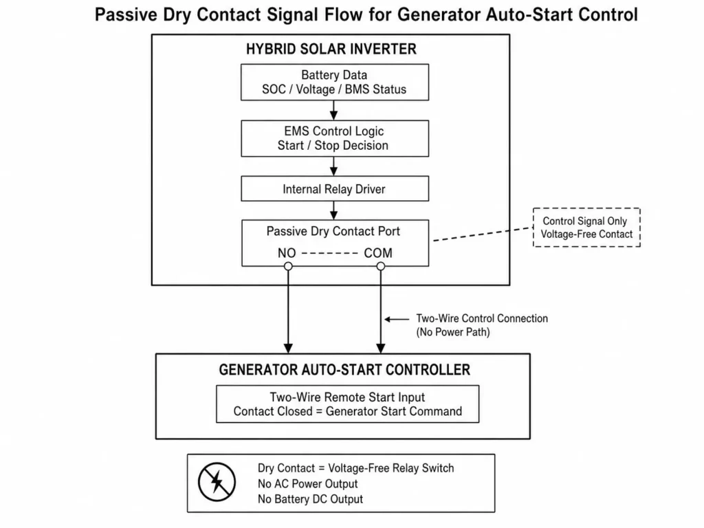
The relay acts strictly as a signal switch, isolated from main AC and DC power paths. System installation and insulation design must meet IEC 62109-1 safety standards.
| Parameter / Feature | Specification / Configuration | Engineering Description |
| Relay Type | Passive Dry Contact | Voltage-free interface for external generator control |
| Terminal Designations | NO (Normally Open), COM (Common), NC (Normally Closed) | Two-wire auto-start systems commonly use NO and COM |
| Control Function | Generator Start / Stop Signal | Switches the external generator controller’s control circuit |
| Power Circuit Function | Not Applicable | Dry contact terminals must not carry generator output or battery power |
| Electrical Rating | Refer to inverter manual | Keep control-circuit voltage and current within specified contact limits |
Running generator output or battery power through dry contacts causes contact welding and permanent hardware failure. Only switch the designated two-wire control circuit within the inverter’s specified contact ratings.
Haven Deer hybrid inverters integrate dry contact control into the Energy Hub to automate generator operation. The inverter’s EMS monitors programmed battery criteria to drive the auto-start process.
Learn more about Automated Generator Integration via Passive Dry Contact
2. Electrochemical Physics: Why LiFePO4 Flat Voltage Curves Deceive Open-Loop Inverters
Open-loop voltage triggers cause premature generator starts because LiFePO4 cells maintain flat discharge curves across most of their capacity, rendering terminal voltage an unreliable SoC indicator. Under dynamic electrical loads, voltage-only sensing fails to distinguish between transient voltage sag and actual battery depletion.
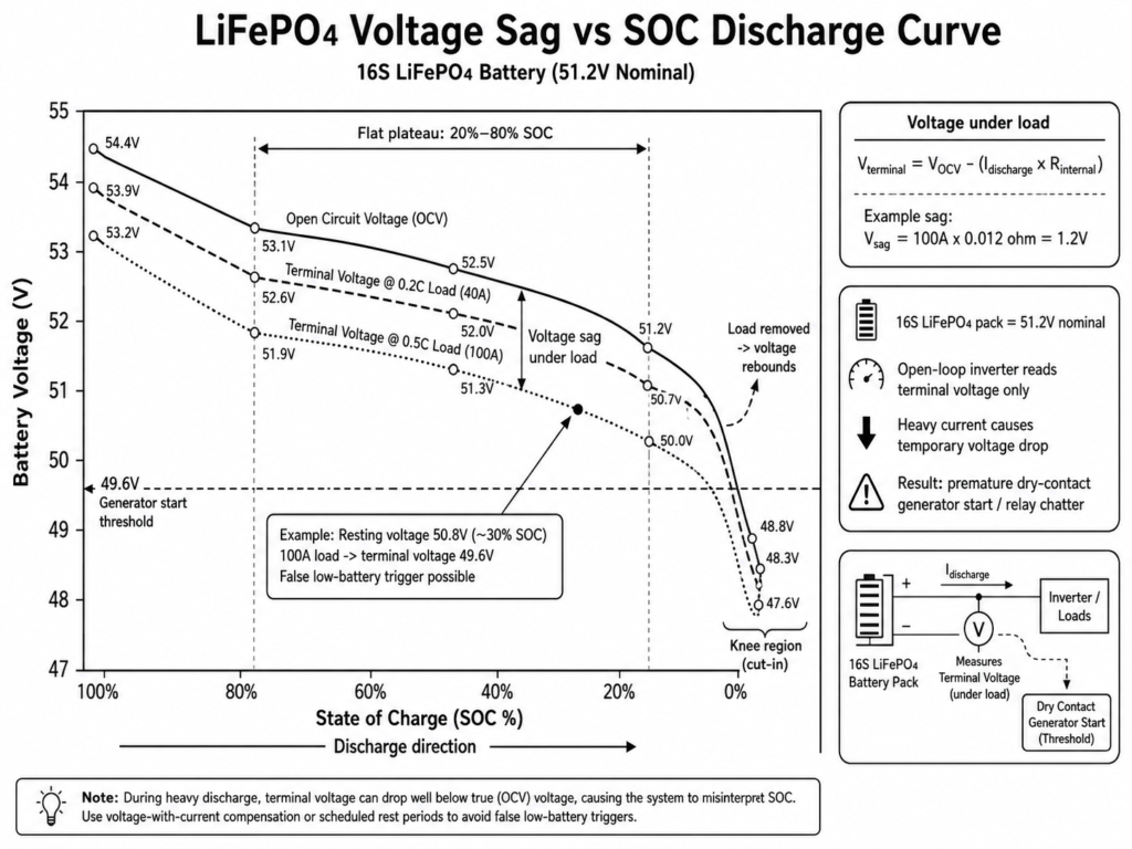
A standard 48V nominal battery architecture uses a 16S (16 cells in series) LiFePO4 configuration, yielding a nominal voltage of 51.2V (16 × 3.2V/cell). Between 20% and 80% SoC, a 16S pack’s Open Circuit Voltage (OCV) spans a narrow window, making voltage-based SoC tracking inaccurate. Without closed-loop BMS communication, an open-loop inverter evaluates system status using only measured terminal voltage.
Terminal voltage under load follows this equation:
V_terminal = V_OCV – (I_discharge × R_internal)
Where:
V_terminal = Battery terminal voltage measured at the inverter DC input (V)
V_OCV = Open-circuit voltage of the battery bank at rest (V)
I_discharge = Battery discharge current, including continuous load or transient surge current (A)
R_internal = Total resistance from battery cells, internal busbars, cables, and connection points (Ω)
High discharge current across cell, busbar, and cable resistance causes immediate voltage sag.
For example, assuming a 16S 200Ah battery bank has a total current-path resistance of 12mΩ (0.012Ω), a 100A inverter surge load produces the following terminal voltage drop:
V_sag = 100A × 0.012Ω = 1.2V DC
If the battery’s resting voltage is 50.8V (~30% SoC), drawing 100A temporarily reduces terminal voltage to approximately 49.6V. The open-loop inverter misinterprets this transient drop as battery depletion, triggering the dry contact prematurely. When load drops, voltage recovers—causing relay chatter and generator short-cycling.
| 16S LiFePO4 Operating Region | Typical OCV Range | Voltage Under Load | SoC Reference Range |
| Fully Charged Region | Around 54.4V | Depends on charging and load conditions | Near 100% |
| Upper Plateau | Approximately 53V range | Reduced by load current and resistance | Around 70%–90% |
| Mid-Discharge Plateau | Approximately 52V range | Sensitive to discharge current | Around 30%–70% |
| Lower Plateau | Approximately 51V range | Voltage sag becomes more noticeable | Around 15%–30% |
| Discharge Knee Region | Below approximately 49V | Rapid voltage decline under load | Low SoC region |
Common Mistake: Setting start thresholds based solely on resting OCV causes false triggers during load spikes. Motor startup currents and sudden load shifts briefly pull down terminal voltage, activating backup generators far earlier than required.
Haven Deer battery systems, including AL-WM512100 (5.12kWh), AL-WM512200 (10.24kWh) wall-mounted modules, and MB512300 (15.0kWh) floor-standing mobile cabinets, feature Master BMS controllers that stream real-time cell voltage, current, and status data. Closed-loop communication drives accurate SoC-based generator triggers, eliminating false starts from voltage sag.
Find out more about Grade A LiFePO4 Prismatic Cells in Off-Grid Solar Kits
3. Setting Thresholds in Closed-Loop Systems (BMS-Driven SOC % Triggering)
Closed-loop generator auto-start relies on CAN bus protocols or RS485 links between the BMS and the hybrid inverter EMS. The BMS feeds digital SoC and telemetry to the EMS, which operates the dry contact relay based on real-time data instead of terminal voltage.
The BMS tracks SoC via Coulomb counting, integrating cell voltages, temperatures, and current over time. The inverter reads this bus data to execute programmed generator start and stop thresholds. Transient load surges do not alter reported SoC, preventing false triggers.
| Operational Strategy | Generator Start Threshold (SoC %) | Generator Stop Threshold (SoC %) | Low-SoC Delay Timer | Recommended Scenario |
| Standard Off-Grid Self-Consumption | 20% | 80% | 10 seconds | Residential off-grid homes with daily solar PV generation |
| Deep Discharge Protection Mode | 15% | 85% | 10 seconds | High-reliability remote cabins or critical backup applications |
| Solar Shortfall Backup Mode | Site autonomy requirements | Configured recovery SoC level | Based on system design | Extended cloudy periods or sites requiring higher backup reserves |
Engineering Tip: Setting the generator stop threshold at 80%–85% SoC maximizes fuel efficiency and cuts running costs. Above 80% SoC, LiFePO4 charging enters a constant-voltage phase with diminishing energy acceptance per generator hour. Stopping early leaves headroom to store PV energy when solar generation resumes.
The Haven Deer ALL 4812000 Pro 12kW hybrid inverter uses CAN/RS485 communication with compatible LiFePO4 batteries to drive precise, EMS-managed dry contact triggering.
Get more details on Open-Loop vs. Closed-Loop BMS-Inverter Communication
4. Setting Thresholds in Open-Loop Systems (Voltage Triggering & Hysteresis Math)
Open-loop systems trigger dry contacts using measured terminal voltage. Set voltage hysteresis and a delay timer to prevent false starts during motor inrush currents.
Voltage hysteresis defines the gap between start and stop thresholds:
ΔV_hysteresis = V_stop – V_start
Where:
V_stop = Programmable generator cut-out terminal voltage (V)
V_start = Programmable generator cut-in terminal voltage (V)
ΔV_hysteresis = Voltage difference between stop and start thresholds (larger hysteresis prevents relay chatter)
For a 48V (16S) nominal LiFePO4 battery bank, installers can use the following engineering reference parameters:
- Cut-in Voltage (V_start): 48.8V DC (~3.05V/cell for 16S LiFePO4). True SoC at this voltage varies with load, temperature, and internal resistance.
- Cut-out Voltage (V_stop): 54.4V DC (~3.40V/cell for 16S LiFePO4). Match final charging cut-off to manufacturer specifications.
- Low-Voltage Delay Timer: 30 to 60 seconds. Requires sustained voltage below V_start before triggering the relay.
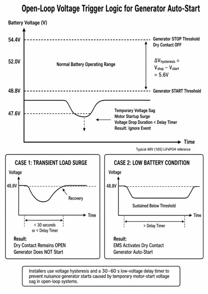
Inductive loads like well pumps cause transient voltage sags below V_start. A 30–60 second delay timer ignores these brief dips, preventing false starts.
| System Profile / Load Condition | Recommended Configuration Approach | Engineering Consideration |
| Light Residential Loads | Use a higher start voltage threshold with appropriate delay filtering | Lower current demand produces less voltage sag |
| Standard Off-Grid Loads | Configure voltage hysteresis and delay based on battery capacity and inverter load profile | Balance battery protection and generator runtime |
| Heavy Inductive Loads | Use a lower start threshold with longer delay filtering when voltage sag is expected | Account for motor startup current and transient voltage drop |
Haven Deer hybrid inverters allow direct programming of voltage thresholds and delay timers via the setup interface.
Explore Sizing Diesel/Gas Generators for Off-Grid Battery Recharging
5. Step-by-Step Commissioning Protocol for Generator Auto-Start Integration
Commissioning a dry contact interface requires verifying wiring integrity, confirming parameters, and aligning test procedures with NFPA 110 standby power standards before placing the system into service.
5.1 Commissioning Checklist & Setup Procedure
1. Verify Physical Signal Wiring: Isolate system power before wiring. Connect the generator controller’s two-wire start terminals to inverter NO and COM terminals using signal cable. Confirm zero external AC or DC voltage is present across the dry contacts.
2. Establish Battery Communication Protocol: Select the corresponding CAN or RS485 protocol in the inverter menu for closed-loop battery setups. If battery comms are unavailable, select open-loop voltage mode.
3. Program Start/Stop Logic & Timers:
- Closed-Loop: Set start at 20% SoC and stop at 80% SoC.
- Open-Loop: Set 48.8V DC start, 54.4V DC stop, and a 30-second low-voltage delay for 16S LiFePO4 packs.
4. Configure Generator Engine Timers: Program engine warm-up delays and set minimum generator runtime to prevent short-cycling.
5. Perform Forced Dry Contact Test: Force relay activation via the inverter maintenance menu. Verify contact closure, engine auto-start, and inverter AC input acceptance.
Engineering Tip: Set a minimum generator runtime in the EMS. Short-cycling prevents engines from reaching operating temperature, causing incomplete combustion, moisture buildup, and starter wear.
| Verification Step | Target Inspection Criteria | Pass/Fail Standard |
| Signal Cable Continuity | Cable connected between NO/COM and start terminals | Continuity confirmed when closed; open circuit when inactive |
| Voltage Leakage Check | Test passive dry contact terminals before wiring | 0V AC/DC measured across dry contacts |
| Delay Timer Verification | Transient voltage drop shorter than programmed delay | Relay remains open during brief sags |
| System Sync & Charge | Inverter locks to generator AC voltage and frequency | Inverter accepts AC input and initiates battery charge |
| Automated Shutdown | Battery reaches programmed stop threshold | Relay opens; generator initiates cool-down and shutdown |
Haven Deer Solar ESS Kits simplify commissioning by pre-integrating compatible inverter, battery, and generator dry contact protocols.
Dive deeper into Commissioning Checklist for Installers: First-Time Setup
6. Common Field Engineering Pitfalls & Diagnostic Troubleshooting
Automated generator start failures in off-grid BESS usually stem from improper dry contact wiring, bad trigger settings, communication loss, or controller faults.
| Failure Symptom | Probable Root Cause | Field Engineering Solution |
| Generator starts but shuts off shortly after startup | Unconfigured minimum runtime or premature start-signal release upon initial battery recovery. | Set minimum generator runtime in the EMS and adjust start/stop hysteresis logic. |
| Generator fails to crank when threshold is reached | Wrong dry contact terminal selection, faulty two-wire start wiring, or damaged signal cable. | Confirm wiring against the inverter schematic. Perform a forced relay test to verify NO/COM contact closure. |
| Relay chatters rapidly on motor startup | Open-loop voltage sensing reacts to transient voltage sag from inrush currents. | Increase voltage hysteresis and set a 30–60 second low-voltage delay timer. |
| Generator cranks but controller shows lockout fault | Engine fails to start due to fuel starvation, ignition failure, or internal controller lockout. | Check fuel and engine status. Confirm the dry contact start signal remains closed during cranking. |
| Generator continues running after battery recovery | Misconfigured stop threshold, latched control logic, or relay contact welding from overcurrent. | Check stop thresholds and measure contact continuity. Ensure the relay only switches low-voltage control circuits. |
7. Frequently Asked Questions
What is a dry contact signal on a hybrid solar inverter?
A dry contact is a passive, voltage-free relay interface (NO/COM/NC) inside the inverter. It opens or closes an external control circuit to signal an auto-start generator without supplying internal power.
Why is SOC triggering preferred over voltage triggering for LiFePO₄ batteries?
LiFePO4 batteries maintain a flat discharge curve across most of their capacity. Load spikes cause transient voltage sag, whereas closed-loop BMS communication provides accurate, real-time SoC telemetry.
What is the recommended generator start voltage for a 48V (16S) LiFePO₄ battery?
For a 16S LiFePO4 pack, set the generator start voltage to 48.8V DC (~3.05V/cell). True SoC at this voltage varies with load current, cell temperature, and internal resistance.
Why do heavy electrical loads cause premature generator starts in open-loop mode?
Heavy current draw causes immediate voltage sag (V_sag = I × R_internal). The inverter misinterprets this brief terminal drop as battery depletion, triggering the generator early.
How does a low-voltage delay timer prevent generator short-cycling?
The timer requires sustained voltage below the start threshold before closing the relay—ignoring brief sags and preventing short-cycling.
Why should generator charging stop at 80% SOC instead of 100%?
Stopping at 80%–85% SoC avoids the slow constant-voltage charging phase, cutting fuel use. It leaves headroom to store PV energy when solar resumes.
Can 230V AC generator power be wired directly through the dry contact port?
No. Dry contacts switch low-voltage signal circuits only. Running 230V AC power through dry contact terminals causes contact welding and relay failure.
What is the difference between NO and NC dry contact terminals?
NO (Normally Open) contacts close when activated, completing the circuit. NC (Normally Closed) contacts open when activated, breaking the circuit. Select terminal configuration based on generator controller requirements.
How do Haven Deer hybrid inverters manage dry contact control logic?
Haven Deer hybrid inverters integrate dry contacts directly into EMS control logic. Systems run closed-loop SoC triggers over CAN/RS485 or fall back to open-loop voltage thresholds.
Why is a minimum generator runtime setting necessary?
It prevents engine short-cycling, allowing the generator to reach stable operating temperatures and avoid incomplete combustion.
What cable type should be used for dry contact signal wiring?
Use a two-core low-voltage signal cable. In high-EMI environments, run shielded twisted-pair wire compliant with IEC 61000 EMC standards.
What happens if BMS communication drops during closed-loop operation?
If BMS comms drop, the inverter triggers a communication-loss fault and falls back to pre-programmed open-loop voltage thresholds. Learn more about AC Input Sharing: Grid vs. Backup Generator Switching.
8. Need Engineering Support for Your Off-Grid Generator Integration System?
Prevent generator short-cycling, bad trigger thresholds, and BMS integration failures. Consult Haven Deer application engineers to validate dry contact control logic, battery sizing, inverter settings, and off-grid BESS architecture.
Contact Us for a Customized Solution