Quick Answer: Managing 12,000VA to 22,000VA surge events off-grid requires exact matching: you must align the locked-rotor current (I_LRC) of inductive loads with the available inverter surge power (typically rated for 5 seconds) and the BMS peak discharge limit. Inductive loads like water pumps and HVAC compressors pull 3× to 7× their running current at startup, triggering massive apparent power spikes. Building a reliable off-grid solar power system architecture requires validating AC inverter kVA output and DC battery current delivery simultaneously. Both sides must clear the surge.
1. The Physics of Inductive Inrush Currents in Off-Grid Microgrids
In off-grid microgrids, AC loads fall into two distinct physical electrical categories: resistive loads and inductive loads. Resistive loads—electric heaters, incandescent lighting, and heating elements—draw linear current. Their startup current equals continuous running current, operating at unity power factor (cos φ = 1.0).
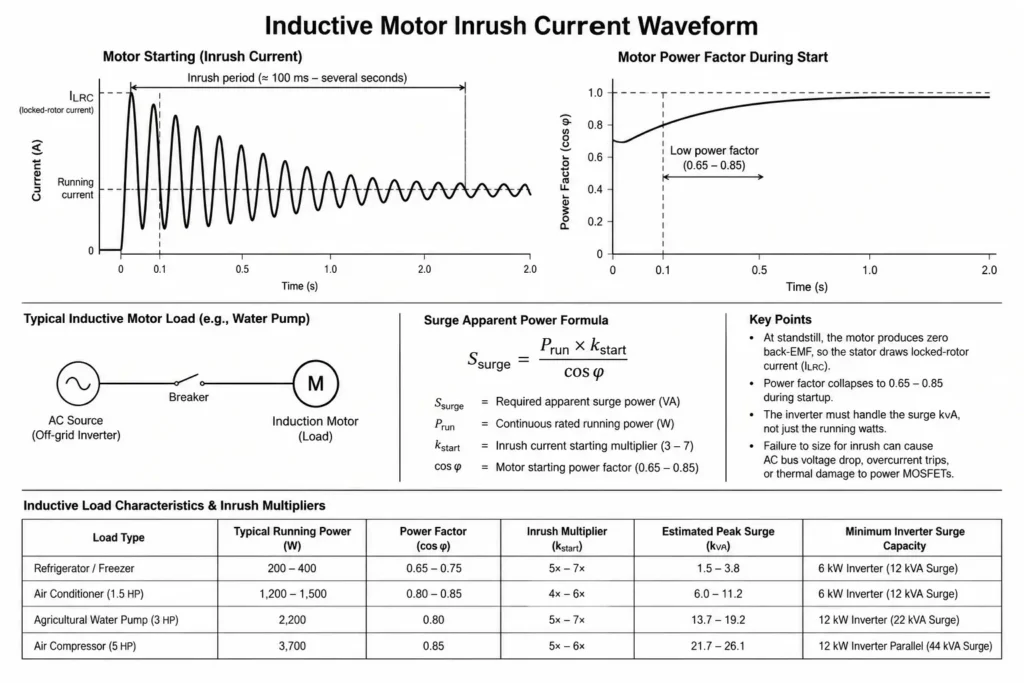
Inductive loads—including deep-well water pumps, refrigeration compressors, air conditioners, air compressors, and heavy farm machinery—rely on electromagnetic induction to rotate electric motors. At standstill, an AC motor produces zero back-electromotive force (back-EMF) to choke incoming current.
Ssurge = (Prun × kstart) / cos φ
Where:
- Ssurge = Required apparent surge power in Volt-Amperes (VA)
- Prun = Continuous rated running active power in Watts (W)
- kstart = Inrush current starting multiplier (typically 3 to 7)
- cos φ = Motor starting power factor (typically 0.65 to 0.85)
Across the first 100 milliseconds to several seconds, the stator pulls locked-rotor current (ILRC). Motor power factor collapses simultaneously to 0.65–0.85. This drives a massive instantaneous kVA demand into the off-grid inverter. Sizing an off-grid solar power system strictly on running watts causes instant failure. The locked-rotor surge will drop inverter AC bus voltage, trip overcurrent protections, or thermally cook the power MOSFETs.
1.1 Inductive Load Characteristics & Inrush Multipliers
| Load Type | Typical Running Power (W) | Power Factor (cos φ) | Inrush Multiplier (kstart) | Estimated Peak Surge (kVA) | Minimum Inverter Surge Capacity |
| Refrigerator / Freezer | 200 W – 400 W | 0.65 – 0.75 | 5× – 7× | 1.5 kVA – 3.8 kVA | 6 kW Inverter (12 kVA Surge) |
| Air Conditioner (1.5 HP) | 1,200 W – 1,500 W | 0.80 – 0.85 | 4× – 6× | 6.0 kVA – 11.2 kVA | 6 kW Inverter (12 kVA Surge) |
| Agricultural Water Pump (3 HP) | 2,200 W | 0.80 | 5× – 7× | 13.7 kVA – 19.2 kVA | 12 kW Inverter (22 kVA Surge) |
| Air Compressor (5 HP) | 3,700 W | 0.85 | 5× – 6× | 21.7 kVA – 26.1 kVA | 12 kW Inverter Parallel (44 kVA Surge) |
Quantifying these startup multipliers prevents costly field truck rolls. For technical details on how waveform distortion affects motor torque and heat buildup during startup, see Pure Sine Wave vs Modified Sine Wave for Inductive Motor Loads.
2. Sizing Inverter Surge Power: 12,000VA vs 22,000VA Limits
Inverter nameplates split into two primary operational ratings: Continuous Active Power (kW) and Peak Short-Time Surge Apparent Power (kVA). Transformerless hybrid inverters rely on high-frequency switching stages engineered to ride through brief overloads defined by a thermal trip curve:
- 100% to 110% Load: Continuous operation.
- 110% to 150% Load: Sustained for 10 seconds before overload protection trips.
- 150% to 200% Load: Sustained for 5 seconds (Peak Surge Window).
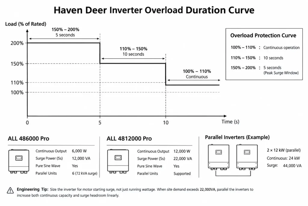
The inverter’s 5-second surge capacity must clear the motor’s starting apparent power (Ssurge). Surge capacity dictates motor survival.
The Haven Deer ALL 486000 Pro hybrid solar inverter delivers 6,000W continuous output with a 12,000VA 5-second surge envelope. This handles single residential motor loads like 1.5 HP air conditioners or well pumps.
For commercial farms, agricultural irrigation, or large off-grid villas with heavy inductive machinery, the Haven Deer ALL 4812000 Pro steps up to 12,000W continuous output and a peak surge capacity of 22,000VA for 5 seconds.
2.1 Haven Deer Inverter Surge Capacity Matrix
| Parameter | ALL 486000 Pro | ALL 4812000 Pro |
| Rated Continuous Output Power | 6,000 W | 12,000 W |
| Maximum Surge Power Rating | 12,000 VA | 22,000 VA |
| Surge Duration Limit | 5 seconds | 5 seconds |
| Pure Sine Wave Output | Yes (220/230/240V) | Yes (220/230/240V) |
| Dual AC Output (Smart Load Shedding) | Supported | Supported |
| Max Parallel Units | 6 units (72 kVA surge) | Supported (Parallel expansion) |
Engineering Tip: Never size an off-grid inverter exclusively on continuous running wattage when motors are present. Sizing only for running loads guarantees nuisance trips and thermal MOSFET failure during startup.
When site startup demand exceeds 22,000VA, parallel the inverters. Paralleling units scales continuous capacity and surge headroom linearly. Connecting two 12 kW units in parallel yields 24 kW of continuous output and 44,000VA of peak surge headroom. Learn more about system architecture options in Single MPPT vs Dual MPPT in Off-Grid Solar Kits.
3. Battery Bank DC Peak Discharge Limits and BMS Threshold Synchronization
Systems trip when engineers size the AC inverter for peak surge but ignore battery DC discharge limits. The DC bus must match the AC surge. Inverters pull instantaneous surge energy straight from the battery bank.
To calculate the instantaneous DC current demand placed on a 48V nominal battery bank during a peak AC surge, apply the following formula:
IDC,peak = Ssurge / (ηinverter × VDC,min)
Where:
- IDC,peak = Instantaneous DC current demand on the battery bank in Amperes (A)
- Ssurge = Total AC surge apparent power in Volt-Amperes (VA)
- ηinverter = Inverter DC-to-AC conversion efficiency (e.g., 0.93)
- VDC,min = Minimum operational DC battery voltage (e.g., 48V DC)
If an off-grid system experiences a 22,000VA surge on a 48V DC architecture at 93% inverter efficiency:
IDC,peak = 22,000 VA / (0.93 × 48 V) = 492.8 A DC
Common Field Mistake: Pairing a 12kW high-surge inverter with a single 100Ah LFP pack. Even if the inverter clears 22,000VA on the AC side, a 300A+ DC spike trips the BMS instantly. The result is an immediate blackout.
Every LiFePO4 module relies on an internal BMS with hardcoded current thresholds. Firmware monitors discharge current across three windows: continuous, short-time overcurrent (e.g., 60 seconds), and peak overcurrent (e.g., 3 seconds). Exceeding the BMS threshold opens internal MOSFETs or contactors immediately. This isolates the cells from thermal stress, but drops the entire DC bus.
3.1 Battery Module Peak DC Discharge Capability and Surge Matching
| Battery Module Model | Rated Capacity | Continuous Discharge | Peak Discharge (Short Duration) | Max Recommended Inverter Surge |
| AL-WM512100 (Wall-Mount) | 100 Ah / 5.12 kWh | 100 A DC | 105 A (60s) / 130 A (3s) | 6 kVA Surge Load |
| AL-WM512200 (Wall-Mount) | 200 Ah / 10.24 kWh | 200 A DC | 210 A (60s) / 260 A (3s) | 12 kVA Surge Load |
| MB512300 (Cabinet) | 300 Ah / 15.0 kWh | 200 A DC | 220 A (60s) / 280 A (3s) | 15 kVA Surge Load |
Supporting a 22,000VA surge requires paralleling battery modules via Master-Slave communication. Paralleling two Haven Deer AL-WM512200 wall-mounted home solar batteries delivers 400A continuous and 520A peak DC discharge for 3 seconds. This safely clears the 492.8A DC demand.
For additional details on selecting wall-mounted battery capacities for high-drain systems, refer to 51.2V 102Ah vs 206Ah Wall-Mounted Battery Modules.
4. Engineering Mitigation Strategies: Soft Starters, VFDs, and Smart Load Shedding
Oversizing inverters and battery banks is not the only fix for inductive spikes. Engineers can suppress startup transients at the motor or manage them via the Energy Management System (EMS).
4.1 Solid-State Soft Starters
Soft starters wire in-line between the inverter AC bus and the motor. They use thyristors (SCRs) to ramp AC terminal voltage gradually. Stretching motor acceleration from milliseconds to several seconds cuts locked-rotor inrush by 50% to 60%. A 15,000VA surge drops to 6,000VA–7,500VA. That cuts required inverter surge power in half.
4.2 Variable Frequency Drives (VFDs)
For deep-well pumps and heavy HVAC compressors, evaluating soft starters vs variable frequency drives reveals clear trade-offs in startup torque and inrush mitigation. A VFD rectifies AC to DC, then synthesizes an adjustable-frequency, adjustable-voltage AC output. Starting at low frequency clamps inrush current to just 100%–120% of full-load amps (FLA). VFDs eliminate locked-rotor inrush entirely.
4.3 Dual Output Smart Load Management
When multiple loads run simultaneously in an off-grid microgrid, a motor startup can exceed total inverter capacity. Haven Deer ALL 486000 Pro and ALL 4812000 Pro inverters address this via Dual AC Output terminals: Main Output and Second (Smart Load) Output.
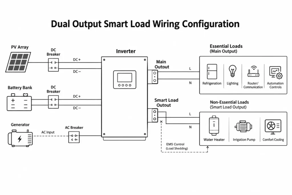
Essential loads—refrigeration, lighting, routers, automation controls—land on the Main Output terminal. Non-essential high-power loads—water heaters, irrigation booster pumps, comfort cooling—wire into the Smart Load terminal. When battery SoC drops or motor starts drive severe AC spikes, the internal EMS sheds the Smart Load terminal instantly. Critical loads stay online.
To explore dual output control logic in detail, see Dual AC Output Inverter Engineering: Main vs Smart Load Management.
5. Step-by-Step Surge Sizing Calculation Method (IEC Compliant)
Field systems trip when sizing relies on guesswork. Sizing high-surge inductive loads requires a strict, two-stage mathematical check across both AC and DC stages.
5.1 Step-by-Step Engineering Example
Project Scenario: An off-grid farm requires continuous power for a 3 HP deep-well pump alongside baseline refrigeration and lighting.
System Parameters:
- Motor Rating: 3 HP (1 HP = 746 Watts) → Active Power Prun = 2,238 W
- Motor Inrush Multiplier (kstart): 5.0
- Motor Starting Power Factor (cos φ): 0.80
- Inverter Efficiency (ηinverter): 93% (0.93)
- Minimum DC Bus Voltage (VDC,min): 48V DC
Step 1: Calculate Total AC Surge Apparent Power (Ssurge)
Ssurge = (Prun × kstart) / cos φ Ssurge = (2,238 W × 5) / 0.80 Ssurge = 11,190 W / 0.80 = 13,987.5 VA ≈ 14.0 kVA
Step 2: Select the Hybrid Inverter Power
- Option A (6 kW ALL 486000 Pro): Continuous output = 6,000W; Peak Surge = 12,000VA for 5 seconds. Result: FAILS (12,000VA < 13,987.5VA). Inverter trips on startup.
- Option B (12 kW ALL 4812000 Pro): Continuous output = 12,000W; Peak Surge = 22,000VA for 5 seconds. Result: PASS (22,000VA > 13,987.5VA). Ample surge headroom.
Step 3: Calculate Peak DC Current Demand (IDC,peak)
IDC,peak = Ssurge / (ηinverter × VDC,min) IDC,peak = 13,987.5 VA / (0.93 × 48 V) IDC,peak = 13,987.5 / 44.64 = 313.3 A DC
Step 4: Determine Battery Bank Configuration
- Single AL-WM512200 Module (200Ah): Continuous discharge = 200A DC; Peak discharge (3s) = 260A DC. Result: FAILS (260A < 313.3A DC). Instant BMS overcurrent disconnect.
- Two AL-WM512200 Modules in Parallel: Continuous discharge = 400A DC; Peak discharge (3s) = 520A DC. Result: PASS (520A > 313.3A DC peak current demand).
Step 5: Minimum Battery Modules Formula
Npacks = IDC,peak / IBMS,peak Npacks = 313.3 A / 260 A = 1.20 → Round up to 2 parallel battery packs. Always round up to whole packs.
5.2 Five-Step Inverter & Battery Surge Verification Checklist
- Verify motor nameplate ratings: Check horsepower (HP) or kilowatts (kW), full-load amps, and standardized NEMA locked-rotor code letters.
- Calculate peak AC surge apparent power (Ssurge): Factor in active running watts, starting current multiplier, and starting power factor.
- Confirm inverter 5-second surge rating: Ensure short-duration kVA capability strictly exceeds Ssurge.
- Convert AC surge to DC current demand (IDC,peak): Calculate peak draw against minimum operational DC bus voltage (48V DC).
- Match parallel BMS discharge limits: Confirm combined battery short-duration peak current rating exceeds IDC,peak with adequate engineering margin.
For the complete sizing methodology covering full PV array, inverter, and storage integration, see Step-by-Step Engineering Guide to Sizing Off-Grid ESS Kits.
6. Field Installation Protocols & Protection Device Sizing
Field reliability under heavy surge loads hinges on two physical components: breaker trip curves and DC conductor sizing. Under-sizing either triggers instant nuisance trips.
6.1 Circuit Breaker Trip Curves (Type C vs Type D)
Miniature circuit breakers (MCBs) calibrated to IEC 60898-1 tripping characteristics use dual thermal-magnetic trip mechanisms. Type B and C curves trip prematurely under motor inrush. Inductive motor circuits demand Type D breakers.
- Type C Breakers: Magnetic trip triggers at 5× to 10× rated current (In). Inrush spikes easily cross this threshold, tripping the breaker during startup.
- Type D Breakers: Magnetic trip triggers at 10× to 20× rated current (In). They ride through startup spikes while preserving overload protection against sustained faults.
6.2 DC Cable Sizing & Voltage Drop Rules
Severe DC current spikes during startup induce immediate voltage drops across battery cables. Excessive cable resistance pulls terminal voltage below the inverter’s low-DC cutoff (typically 40.0V DC). The inverter shuts down instantly.
- Keep DC cable voltage drop strictly below 2.0% at peak surge current (IDC,peak). Voltage drop starves inverters.
- For 300A+ peak surge with runs under 2 meters, install flexible fine-stranded copper cables sized at 70 mm² to 95 mm² (2/0 to 3/0 AWG).
- Crimp all terminal lugs with hydraulic hex dies and torque bolts to factory spec. Loose lugs cause localized I²R overheating.
Engineering Tip: Never run inductive compressor circuits on standard residential Type C breakers. Specify Type D breakers on dedicated motor distribution sub-panels to clear inrush spikes without compromising thermal protection.
6.3 Pre-Commissioning Protection Device Checklist
- Confirm Type D circuit breakers protect all dedicated inductive motor branch circuits.
- Verify DC battery cable gauge limits total voltage drop under 2.0% at peak DC current drain (IDC,peak).
- Check master-slave DIP switch address settings and CAN/RS485 communication cables between parallel battery packs.
- Verify DC fast-acting fuses (or rated DC circuit breakers) match the total peak surge capability of the parallel battery bank.
- Inspect Dual AC Output wiring to verify essential loads are isolated on the Main Output terminal.
For field commissioning protocols and first-time turn-on procedures, consult Commissioning Checklist for Installers: First-Time Setup.
7. Frequently Asked Questions
Why does my off-grid hybrid inverter trip on overload when a motor starts, even if the running wattage is low?
Motors pull locked-rotor current (ILRC) reaching 3× to 7× continuous running current at startup. If this peak apparent power spike exceeds the inverter’s 5-second surge window, overcurrent protection trips immediately to protect switching semiconductors. Always size for peak startup, not running watts.
What is the difference between continuous output power and surge power in off-grid inverters?
Continuous active power (kW) is the sustained thermal output an inverter delivers indefinitely under ambient conditions. Surge apparent power (kVA) is the short-duration envelope—typically 5 seconds—engineered to ride through inductive motor inrush currents. Continuous power runs the motor; surge power starts it.
How does the battery BMS limit the peak surge handling of an off-grid system?
AC surge demand pulls instantaneous DC current spikes directly from the battery bank. If DC surge draw exceeds BMS thresholds (e.g., 130A for 3 seconds on a 100Ah pack), internal protection MOSFETs open immediately. The DC bus drops to zero, triggering an inverter low-voltage shutdown.
Can I use a soft starter on an off-grid solar system to reduce motor inrush current?
Yes. Soft starters use thyristors (SCRs) to ramp motor terminal voltage gradually, cutting locked-rotor inrush by 50% to 60%. This reduces the instantaneous kVA spike on the inverter without dropping mechanical starting torque.
How do I calculate the DC surge current demand on my 48V battery bank?
Divide the required AC surge apparent power (Ssurge) by the product of inverter efficiency (η) and minimum operational DC bus voltage (VDC,min):
IDC,peak = Ssurge / (ηinverter × VDC,min)
Example for a 12,000VA surge: IDC,peak = 12,000 VA / (0.93 × 48 V) = 268.8 A DC
How many parallel battery modules are needed to support a 22,000VA surge inverter?
A 22,000VA surge pulls 492.8A DC at a 48V cutoff voltage. Paralleling two Haven Deer AL-WM512200 (200Ah) modules delivers 400A continuous and 520A peak discharge for 3 seconds. Two modules clear this surge safely.
What is Dual Output Smart Load Management and how does it help with surge loads?
Haven Deer Dual AC Output segregates critical circuits (Main Output) from heavy non-essential loads (Smart Load). When inductive motors start or battery SoC drops, the internal EMS sheds the Smart Load terminal instantly. Critical circuits stay energized.
Does a Variable Frequency Drive (VFD) eliminate motor starting surge?
Yes. A VFD synthesizes variable frequency and voltage to accelerate the motor smoothly. It clamps starting current to 100%–120% of full-load amps (FLA), eliminating the violent 5× to 7× locked-rotor surge entirely.
How long can Haven Deer Pro series inverters sustain maximum surge power?
Haven Deer ALL 486000 Pro and ALL 4812000 Pro hybrid inverters sustain peak surges of 12,000VA and 22,000VA for up to 5 seconds. This window easily clears standard motor acceleration curves.
Can parallel inverter configurations increase surge output capacity?
Yes. Paralleling hybrid inverters scales continuous capacity and surge headroom linearly. Connecting two 6 kW ALL 486000 Pro inverters yields 12 kW continuous output and 24,000VA peak surge capacity.
Why is pure sine wave output essential for high-surge inductive loads?
Modified sine waves introduce severe total harmonic distortion (THD). Harmonics cause counter-torque and eddy-current overheating in motor windings, causing motors to stall or buzz during startup. Pure sine waves deliver clean magnetizing flux.
Which circuit breaker type should be used for motor circuits connected to an off-grid inverter?
Use Type D miniature circuit breakers (MCBs). Type D breakers feature a high magnetic trip threshold of 10× to 20× rated current (In), allowing them to ride through motor starting transients without nuisance tripping. Standard Type C breakers trip prematurely.
8. Technical Support & Custom Engineering Sizing
Surge sizing demands matching four interdependent stages: motor inrush curves, inverter kVA headroom, BMS DC discharge thresholds, and AC trip curves. Miss one, and the microgrid drops.
For residential, agricultural, or commercial projects running heavy inductive equipment, contact Haven Deer application engineering. Our team delivers direct System Sizing Verification & Single-Line Diagram Reviews to validate inverter headroom, battery rack C-rates, and breaker curves before equipment arrives on site.