Quick Answer: Solar inverter transfer time is the duration a hybrid inverter takes to detect a grid failure and switch critical loads to battery or PV backup. Standard IT server power supplies feature an internal hold-up time of roughly 16ms under rated conditions. A 10ms transfer time provides enough margin to prevent server resets during blackouts.
1. The Physics of Solar Inverter Transfer Time: Grid Outages vs. Server Power Supplies
1.1 What Happens During a Grid Interruption?
When grid failure occurs, the AC waveform collapses or drifts outside acceptable voltage and frequency limits. Standard electrical loads like lighting or resistive heaters tolerate short interruptions without issue. However, critical IT servers and processors are highly sensitive to voltage drops—even brief outages trigger system resets.
In grid-tied mode, a hybrid inverter routes utility power directly to critical loads through an internal bypass switch. When grid power drops, the inverter executes a three-step handover sequence:
- Detect utility AC voltage failure or frequency instability.
- Open the AC grid disconnect relay to prevent islanding and backfeeding.
- Fire the DC-to-AC inverter stage and synchronize output before taking over critical loads.
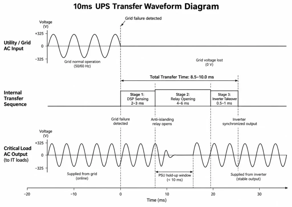
If this sequence exceeds PSU hold-up capability, downstream AC voltage collapses. IT hardware relies on PSU bulk capacitors to bridge this gap.
1.2 Defining Transfer Time: Detection, Relay Opening, and Inverter Phase-Matching
According to IEC 62040-3 performance standards for UPS transfer time, overall switching covers more than mechanical relay travel—it mandates strict dynamic compliance across sensing delay, contact separation, and PWM bridge activation.
- DSP Sensing & Detection Delay (2–3ms): The Digital Signal Processor (DSP) samples grid voltage and frequency continuously. Once RMS values cross configured trip thresholds, the DSP flags the fault and triggers transfer.
- Relay Mechanical Disconnect (4–7ms): Physical relay contacts take time to separate from grid terminals and engage the backup path. Mechanical travel accounts for most of the transfer lag.
- Inverter Bridge Activation & Phase Synchronization (<1ms): The PWM bridge energizes instantly, matching voltage amplitude and phase angle to stabilize power delivery.
| Switching Sequence Stage | Operational Mechanism | Average Duration |
| Stage 1: Grid Disruption Sensing | High-frequency DSP voltage and frequency monitoring | 2.0 – 3.0 ms |
| Stage 2: Relay Contact Separation | Physical opening of internal AC transfer relay contacts | 4.0 – 6.0 ms |
| Stage 3: Inverter Output Takeover | PWM bridge activation and AC waveform stabilization | 0.5 – 1.0 ms |
| Total Transfer Time | Combined Detection, Switching, and Takeover Delay | 8.5 – 10.0 ms |
Engineering Tip: Fast grid monitoring minimizes transfer delay. High-speed DSP controllers detect faults within 2ms, keeping overall switching well under the 10ms threshold.
2. ATX Specifications & ITIC Curves: Why Server PSUs Require Fast Transfer Response
2.1 The Math Behind PSU Hold-Up Time
Server power supply behavior dictates required UPS transfer speed. Switched-Mode Power Supplies (SMPS) step down AC mains to low-voltage DC outputs for CPUs, RAM, and storage drives.
During outages, primary DC bulk capacitors supply stored energy to keep the server running. Hold-up time (thold) measures how long the PSU maintains stable DC output after losing AC input.
The theoretical hold-up time relies on stored capacitor energy:
thold = C × (Vdc,1² – Vdc,min²) / (2 × Pload)
Where:
- thold: PSU hold-up time in seconds (s)
- C: Total primary DC bus capacitance in Farads (F)
- Vdc,1: Initial operating voltage of the primary DC bus post-PFC (typically ~380V DC)
- Vdc,min: Minimum DC bus voltage before shutdown protection triggers
- Pload: Active power draw of the server load in Watts (W)
Worked Engineering Example
Consider an enterprise 750W server power supply running at 100% rated load (Pload = 750W) with a primary DC bus capacitance of C = 560μF (0.00056F). Capacitor voltage drops from Vdc,1 = 380V DC to the minimum limit Vdc,min = 300V DC:
thold = 0.00056 × (380² – 300²) / (2 × 750)
thold = 0.00056 × (144,400 – 90,000) / 1500
thold = 30.464 / 1500 = 0.0203 seconds ≈ 20.3ms
A standard 750W PSU at 25°C theoretically yields ~20.3ms of hold-up margin. However, field conditions degrade this buffer:
- Thermal Degradation: High ambient enclosure temperatures reduce capacitor energy storage.
- Capacitor Aging: Electrolytic capacitors lose performance over time, shrinking effective capacitance.
- Component Margins: High-efficiency PSUs use optimized components with tighter hold-up reserves.
Real-world conditions often push actual hold-up time below theoretical limits. The Intel ATX Power Supply Design Guide targets a minimum 16ms hold-up time for stable operation.
Calculate the Transfer Margin (tmargin) to evaluate system tolerance:
tmargin = thold – ttransfer
With a standard 16ms PSU hold-up requirement and a 10ms hybrid inverter transfer speed:
tmargin = 16ms – 10ms = 6ms
A positive margin prevents server resets. Exceeding available hold-up time causes immediate load dropping.
2.2 Analyzing the ITIC Curve for Critical IT Equipment
The Information Technology Industry Council (ITIC) curve defines voltage ride-through limits for IT hardware during grid disturbances.
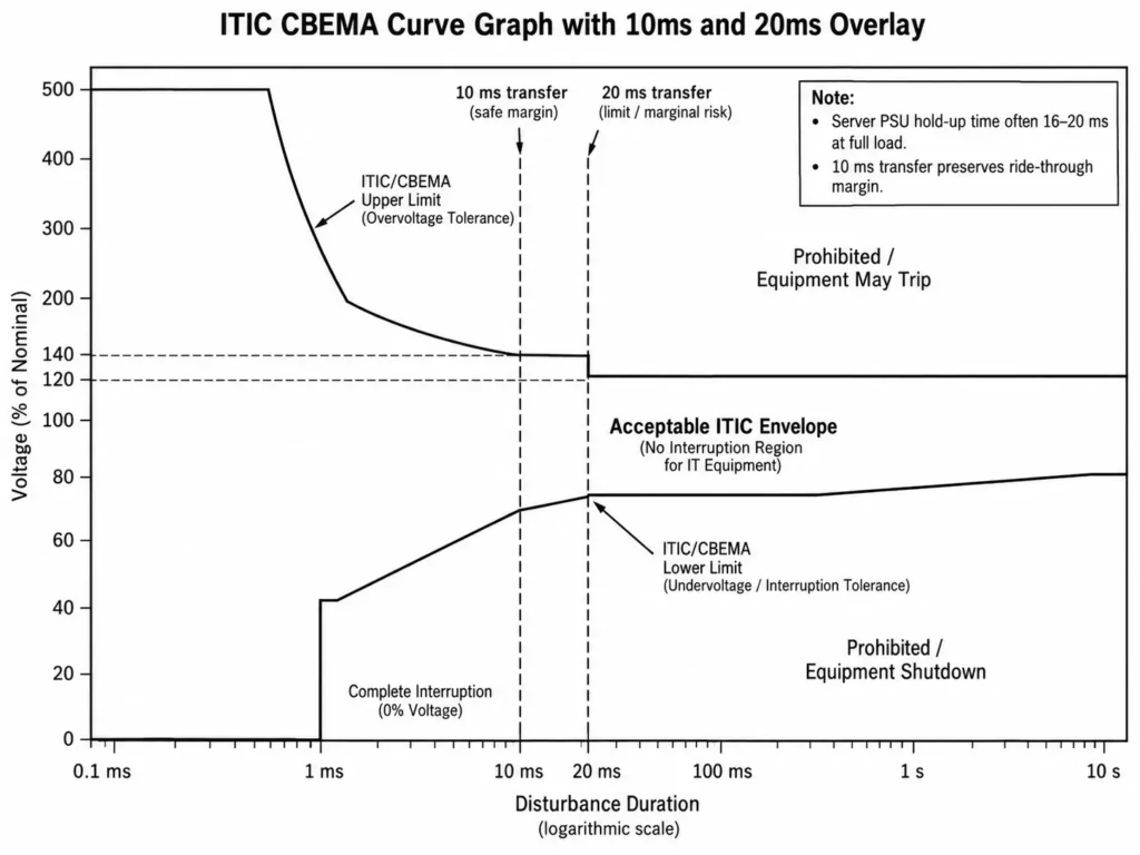
The ITIC curve plots AC voltage against disturbance duration across three regions:
- Maximum Voltage Envelope: Sets upper transient overvoltage thresholds.
- Minimum Voltage Envelope: Sets undervoltage ride-through limits.
- Zero Voltage Zone (Complete Interruption): Sets maximum outage duration before equipment resets or shuts down.
A 10ms transfer keeps grid interruptions within standard IT load tolerances. For complete protection, pair sensitive IT hardware with Dual AC Output load management to isolate server racks from high-inrush motor loads.
| Load Level (% of Rated Load) | Typical PSU Hold-Up Time | 10ms UPS Transfer Result | 20ms Transfer Result |
| 100% Load | 16.0 – 18.0 ms | Safe operating margin | High risk of reboot |
| 75% Load | 20.0 – 22.0 ms | Safe operating margin | Marginal risk |
| 50% Load | 28.0 – 32.0 ms | Safe operating margin | Generally acceptable |
3. 10ms vs. 20ms Transfer Switching: Hardware Dynamics & Solar Architecture
3.1 10ms UPS Mode (Sensitive IT & Server Loads)
Achieving 10ms UPS transfer requires fast DSP grid sensing, low-latency relays, and tuned control firmware. For split-roof or multi-angle arrays, understanding single MPPT vs. dual MPPT helps prevent DC bus voltage drops during dynamic solar shifts.
In 10ms UPS mode:
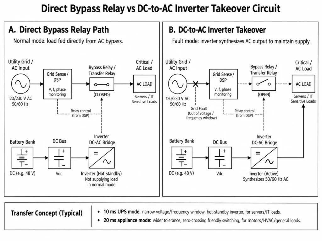
- Tighter Grid Quality Windows: The DSP samples grid voltage and frequency within narrow thresholds. Any boundary trip immediately triggers transfer to protect sensitive electronics.
- Prepared Inverter Output Stage: The DC-to-AC bridge stays energized in hot-standby, enabling instant AC waveform synthesis upon grid isolation.
- Optimized for Sensitive Electronic Loads: Tailored for server racks, telecom gear, networking hardware, and lab equipment that cannot tolerate extended power gaps.
3.2 20ms Appliance Mode (Inductive & Motor Loads)
While 10ms mode protects IT equipment, heavy motor-driven loads require a wider tolerance envelope. Motor loads like HVAC units, pumps, and power tools generate high starting inrush currents and voltage sags.
In 20ms Appliance mode:
- Wider Voltage Tolerance Envelope: The inverter tolerates short voltage dips without transferring, preventing nuisance tripping during motor inrush.
- Relay Protection Consideration: Inductive loads dump stored magnetic energy during disconnect, pitting relay contacts. A 20ms buffer enables zero-crossing switching to prevent arcing and extend relay life.
- Optimized for General Electrical Loads: Ideal for HVAC equipment, lighting circuits, resistive heating, and general loads tolerant of brief switching gaps.
| Technical Parameter | 10ms UPS Mode | 20ms Appliance Mode | Online Double-Conversion UPS |
| Primary Application | Critical servers, IT racks, telecom equipment | Household appliances, HVAC, motors | Mission-critical enterprise IT |
| Transfer Time | ≤10ms | ~20ms | 0ms (Continuous conversion) |
| Target Load Tolerance | Sensitive electronics (<16ms PSU hold-up) | General loads with high dip tolerance | Zero interruption tolerance |
| Grid Voltage Acceptance Range | Narrow window to safeguard sensitive electronics | Wide tolerance to absorb inrush sags | Continuous AC-DC-AC isolation |
| System Efficiency | High efficiency (>95% bypass/inverter) | High efficiency (>95% bypass/inverter) | Lower efficiency (88–92% double conversion) |
| Haven Deer Support | ALL 486000 Pro / ALL 4812000 Pro | ALL 486000 Pro / ALL 4812000 Pro | External Dedicated Topology |
Common Field Mistake: Running IT servers or VoIP gateways in 20ms Appliance mode eats up PSU hold-up margin, causing random reboots. Always match inverter transfer settings to connected PSU hold-up limits.
4. Dual Output Architecture: Protecting Critical Loads via Main Output Isolation
4.1 Main Output (UPS Priority) vs. Smart Load (Second Output)
A 10ms transfer time alone cannot prevent voltage sags if high-inrush motors share a bus with IT servers. Compressors and pumps draw heavy starting currents, pulling down AC output voltage during startup.
Simultaneous motor starting during grid transfer causes AC output sags that can trip sensitive servers. Dual AC Output Architecture solves this by isolating load circuits:
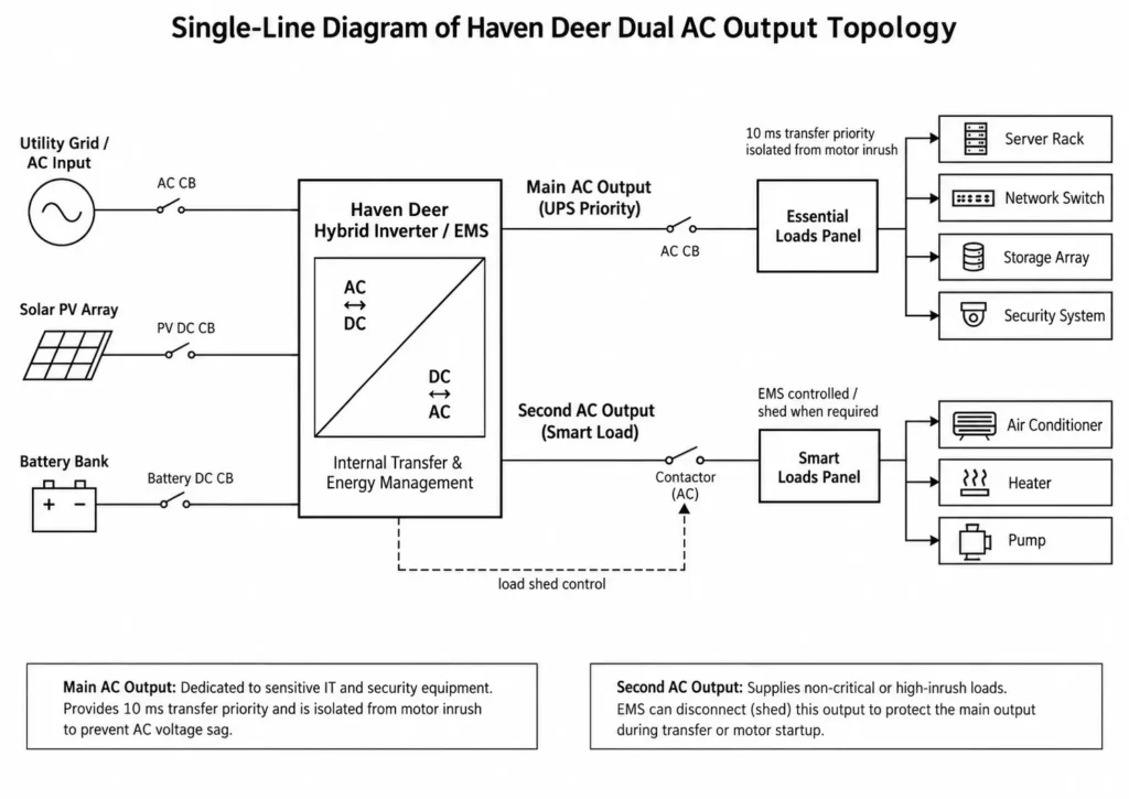
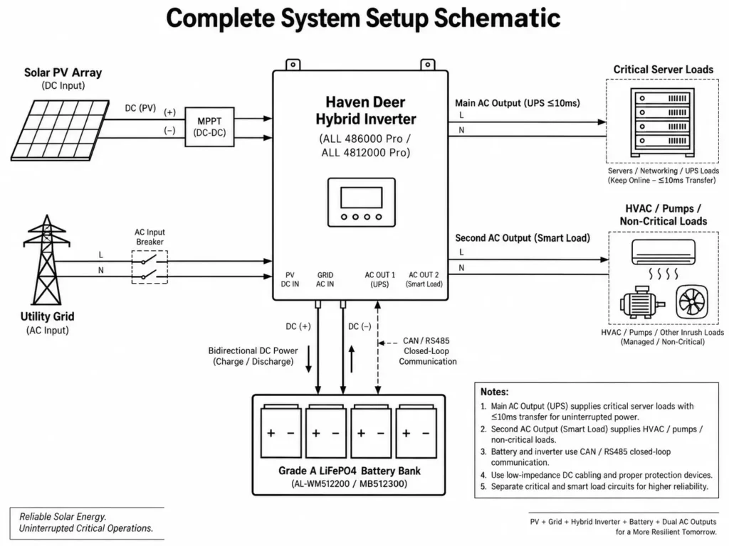
- Main Output Terminal (UPS Priority): Supplies critical loads including servers, network switches, storage arrays, and security systems. This terminal receives transfer priority during grid failure.
- Second Output Terminal (Smart Load): Supplies non-critical or high-inrush loads like air conditioners, heaters, and auxiliary pumps. The inverter manages or sheds this port independently based on operating conditions.
4.2 Preventing Inverter Voltage Sag During High Inrush Loads
When grid failure strikes, the integrated Energy Management System (EMS) monitors system loading. If total demand threatens inverter limits, the internal EMS sheds the Smart Load output to safeguard critical servers. For commercial projects, parallel inverter engineering expands overall capacity while coordinating load protection.
Physical load separation isolates the Main Output from motor startup transients. This maintains clean AC voltage to IT hardware during transfer events.
| Feature | Main AC Output (Essential Loads) | Second AC Output (Smart Load) |
| UPS Transfer Priority | Highest priority for critical loads during grid-to-inverter transfer | Secondary priority with dynamic load control |
| Target Devices | Servers, storage arrays, switches, security systems | Non-critical HVAC, space heaters, pumps |
| Outage Behavior | Continuous supply via battery and PV power | Controlled or shed automatically based on EMS limits |
| Protection Mechanism | Isolated from high-inrush motor transients | Buffers motor starting inrush away from sensitive loads |
Engineering Tip: Hardwire IT racks and network switches to the Main AC Output. Route HVAC and pumps to the Smart Load terminal to keep motor transients off sensitive server rails.
5. System Design & Engineering Best Practices for Uninterrupted Power
5.1 Battery Bank Sizing for Continuous Voltage Stability
DSP firmware controls transfer speed, but battery DC response dictates output voltage stability during transition.
Switching from grid bypass to battery mode within 10ms spikes discharge current. High internal resistance (Rint) causes a severe DC terminal voltage drop via Ohm’s Law:
Vterminal = Voc – (Idischarge × Rint)
Where:
- Vterminal: Actual DC terminal voltage supplied to the inverter terminals (V)
- Voc: Open-circuit battery voltage (V)
- Idischarge: Instantaneous discharge current demand (A)
- Rint: Total equivalent DC resistance of battery cells, cables, busbars, and connections (Ω)
If Vterminal dips below the inverter cutoff, the system trips, dropping AC loads despite a fast transfer setting. Applying a step-by-step engineering guide to sizing off-grid ESS kits prevents these DC bus voltage collapses under peak step-loads.
Engineering Sizing Recommendations for Server Backup:
- Use Grade A LiFePO4 Prismatic Cells: Lithium Iron Phosphate provides low internal resistance and high-discharge stability, preventing DC voltage dips during sudden step loads.
- Establish Closed-Loop Communication (CAN/RS485): Connect BMS to inverter EMS for dynamic current scaling and active SOC tracking rather than inaccurate voltage-based estimates.
- Low-Impedance DC Cabling: Size copper conductors generously to minimize DC resistance and limit voltage drop under peak discharge.
5.2 Haven Deer Hardware Integration (ALL 486000 Pro / ALL 4812000 Pro)
Commercial sites, telecom hubs, and remote offices rely on the off-grid solar power system architecture—pairing high-speed hybrid inverters with Grade A LiFePO4 storage—to guarantee continuous uptime.
- Haven Deer ALL 486000 Pro hybrid solar inverter (6kW Single-Phase): Delivers 9,000W max PV input, 120–500V MPPT range, dual AC outputs, and 10ms UPS transfer for localized backup.
- Haven Deer ALL 4812000 Pro (12kW Dual MPPT): Handles 12kW continuous power, 22kVA surge, dual independent MPPTs (15,000W max PV), and 6-unit parallel scaling.
- Energy Storage Pairing: Pairs with AL-WM512200 (10.24kWh wall-mounted home solar battery) or MB512300 (15.0kWh cabinet off-grid solar battery), featuring Grade A prismatic cells and closed-loop CAN/RS485 integration.
| Peak IT Server Load (kW) | Recommended Hybrid Inverter | Battery Bank Recommendation | Minimum Usable Capacity | Transfer Mode Target |
| 1.0 – 4.5 kW | 1 × ALL 486000 Pro (6kW) | 1 × AL-WM512200 (10.24kWh) | 8.19 kWh @ 80% DoD | UPS Mode ≤10ms |
| 5.0 – 9.5 kW | 1 × ALL 4812000 Pro (12kW) | 1 × MB512300 (15.0kWh) | 12.0 kWh @ 80% DoD | UPS Mode ≤10ms |
| 10.0 – 18.0 kW | 2 × ALL 4812000 Pro (Parallel) | 2 × MB512300 (30.0kWh Total) | 24.0 kWh @ 80% DoD | UPS Mode ≤10ms synchronized |
Pre-Commissioning System Checklist for Critical Server Backup
- Set inverter transfer speed to UPS Mode (≤10ms) via the LCD or monitoring platform.
- Wire server power supply cords exclusively to the Main AC Output terminals.
- Connect high-inrush motor loads (HVAC, pumps) strictly to the Second AC Output (Smart Load).
- Verify CAN/RS485 closed-loop communication cables between battery BMS and inverter EMS are active and online.
- Inspect DC cabling and connection torque to keep voltage drop under load within system limits.
- Execute a live power-cut test under full server load to verify zero-reset transfer.
6. Frequently Asked Questions
Q1: Is 10ms transfer time fast enough to prevent my server from rebooting?
Yes. Enterprise server PSUs feature a 16ms hold-up buffer per ATX standards. A 10ms transfer leaves a 6ms safety margin, preventing reboots during power cuts.
Q2: What is the difference between 10ms UPS transfer and 0ms online double conversion?
A 10ms UPS uses bypass relays to switch loads from grid to inverter upon failure. Online double conversion continuously routes power through AC-DC-AC stages, offering 0ms interruption at the expense of higher thermal losses and lower efficiency.
Q3: Why did my server reboot when connected to a 20ms solar inverter?
A 20ms transfer exceeds the standard 16ms PSU hold-up window. When bulk capacitors drain before the inverter picks up the load, server PSUs drop out and trigger a reboot.
Q4: Can I run heavy inductive loads like air conditioners alongside sensitive servers on a Haven Deer inverter?
Yes. Haven Deer hybrid inverters (ALL 486000 Pro / ALL 4812000 Pro) feature Dual Output terminals. Hardwire critical IT to the Main Output and HVAC to the Second Output (Smart Load) to prevent motor starting inrush from sagging server voltage.
Q5: Does battery health affect transfer time performance?
Battery health does not alter relay switching speed, but high internal resistance or low SoC causes severe DC voltage dips during transfer. Grade A LiFePO4 cells with closed-loop BMS communication ensure stable DC bus voltage under sudden load steps.
Q6: How does Haven Deer achieve a 10ms transfer speed?
High-speed DSPs sample grid AC voltage constantly. When a fault occurs, the DSP flags it within 2ms and fires low-latency mechanical relays to complete handover under 10ms.
Q7: Is 10ms transfer time supported in parallel inverter configurations?
Yes. Parallel units sync through high-speed communication buses, triggering transfer relays simultaneously to maintain sub-10ms handover across all units.
Q8: What happens if grid voltage sags without failing completely?
The DSP triggers transfer when voltage or frequency drops past configured trip limits, isolating the load before severe brownouts hit.
Q9: Does cold ambient temperature affect transfer time performance?
Relay speed remains unchanged, but freezing temperatures increase battery internal resistance. BMS thermal management ensures voltage holds during step transfers.
Q10: How do I configure 10ms UPS mode on Haven Deer inverters?
Select UPS Mode (≤10ms) via the LCD touch interface or mobile monitoring platform.
Q11: Are specialized AC cables required for 10ms UPS setups?
No. Standard copper AC wiring sized to code works. Focus on tight terminal torque and low-impedance ground connections to prevent voltage drops under load.
Q12: How does the ITIC (CBEMA) curve apply to off-grid solar planning?
The ITIC curve plots equipment voltage tolerance against disturbance duration. A 10ms transfer keeps outages inside the zero-voltage ride-through zone, preventing equipment resets.
7. Need to Improve Server Backup Reliability for Your Critical IT Infrastructure?
Send your load profile and single-line diagram (SLD) to Haven Deer application engineers. We evaluate peak inrush, size battery C-rates, and configure tailored complete off-grid solar power system with Dual AC Output isolation to keep your server rails online.