Quick Summary: Inverter parallel operation scales system power by combining up to six hybrid inverter AC outputs onto a single busbar. CAN bus communication coordinates Master-Slave control, synchronizing all units across the shared AC network. Equalizing load distribution prevents damaging circulating currents. Paralleling six 6kW inverters scales continuous AC output to 36kW.
1. Core Electromechanical Principles of Inverter Parallel Operation
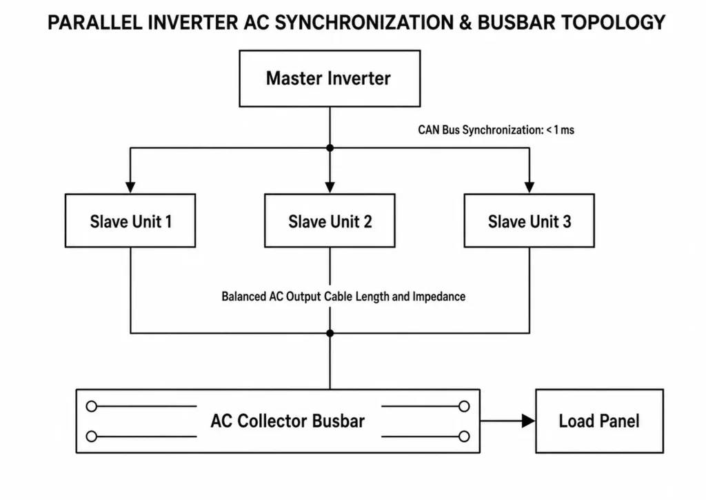
Paralleling low-voltage hybrid inverters within an off-grid solar power system architecture requires active synchronization across a shared AC busbar. Stable load sharing demands matched voltage amplitude, frequency, phase angle, and branch impedance.
1.1 Voltage and Phase Synchronization Requirements
Paralleling hybrid inverters onto a shared AC bus without tripping protection circuits requires continuous alignment across three parameters:
- Voltage Amplitude Differential (ΔV): Minimizing ΔV balances reactive power distribution.
- Frequency Alignment (Δf): Exact frequency matching prevents continuous phase drift.
- Phase Angle Displacement (δ): Precise phase matching eliminates cross-conduction.
In microgrid systems, phase alignment dictates active power sharing, while voltage amplitude controls reactive power distribution. Paralleling an unsynchronized inverter onto a live bus triggers severe current surges, tripping breakers and damaging switching devices.
| Parameter Mismatch | Primary Operational Impact | System Hazard Level | Mitigation Strategy |
| Voltage Differential (ΔV > 1.0V) | Reactive Circulating Current (Qcirc) | Moderate (Thermal stress, reduced efficiency) | Automated voltage feedback tuning via CAN bus |
| Phase Angle Shift (δ > 1.0°) | Active Circulating Current (Pcirc) | Critical (Instantaneous overcurrent trip, component failure) | Internal synchronization control through inverter firmware and communication logic |
| Frequency Drift Beyond Synchronization Limits | Continuous Phase Angle Drift | Critical (Destructive bus short-circuit conditions) | Master inverter synchronization signals transmitted through communication links |
1.2 Mathematical Derivation of Circulating Current (Icirc)
Circulating current (Icirc) flows directly between inverters without supplying the load. Unchecked circulating current burns system capacity and overheats power stages.
The circulating current vector between Unit 1 (V1 ∠ θ1) and Unit 2 (V2 ∠ θ2) connected to a common busbar is calculated as:
Icirc = (V1 ∠ θ1 – V2 ∠ θ2) / (Zline1 + Zline2)
Where:
V1 ∠ θ1 = Output voltage vector of Inverter 1 (V)
V2 ∠ θ2 = Output voltage vector of Inverter 2 (V)
Zline1 = Complex line impedance from Inverter 1 to the collector busbar (Ω)
Zline2 = Complex line impedance from Inverter 2 to the collector busbar (Ω)
Worked Engineering Calculation Example:
Consider two 6kW off-grid hybrid inverters tied to a 230V AC collector busbar with line impedances Zline1 = Zline2 = 0.05 Ω (purely resistive AC cable run).
Unit A Output: 231.0V AC, Phase Angle θ1 = 0.0° (231.0 + j0.0 V)
Unit B Output: 229.0V AC, Phase Angle Drift θ2 = 0.5° (229.0 cos(0.5°) + j229.0 sin(0.5°) = 228.99 + j1.998 V)
Calculating the voltage difference vector (ΔV):
ΔV = (231.0 – 228.99) – j1.998 = 2.01 – j1.998 V
Magnitude of voltage difference (|ΔV|):
|ΔV| = √((2.01)² + (-1.998)²) = √(4.0401 + 3.992) = 2.834 V
Calculating total circulating current (Icirc):
Icirc = |ΔV| / (Zline1 + Zline2) = 2.834 V / (0.05 Ω + 0.05 Ω) = 2.834 V / 0.10 Ω = 28.34 A
A 2.0V voltage offset and 0.5° phase drift produce 28.34A of cross-current. Parasitic circulating current wastes 6.5kW of inverter capacity.
The Haven Deer ALL 486000 Pro hybrid solar inverter relies on high-speed CAN-bus control to synchronize phase angles and eliminate circulating currents.
2. Communication Topology: Master-Slave Control Loop & CAN Bus Architecture
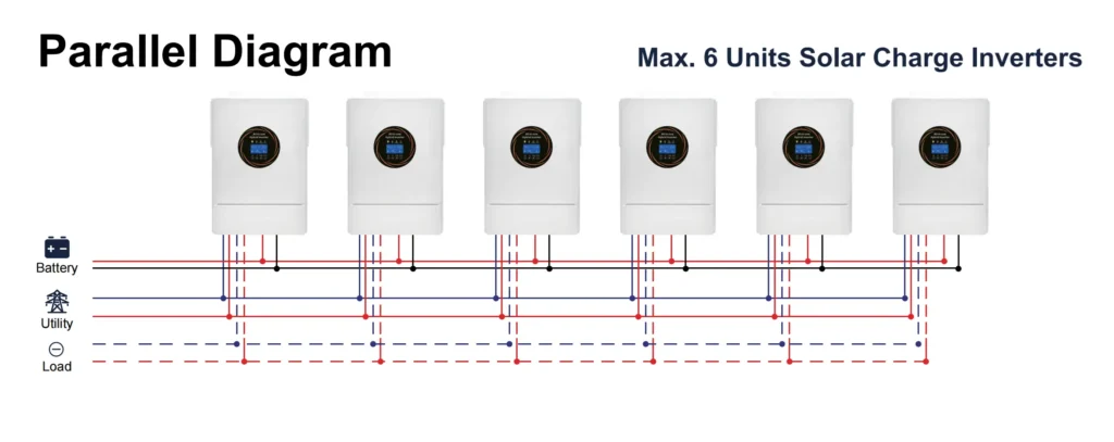
Parallel hybrid inverters rely on Master-Slave CAN architecture for high-speed multi-unit coordination.
2.1 Master Unit Election & Redundancy Logic
A single inverter acts as the Master Controller, driving all secondary Slave units across the CAN bus.
Master Controller Responsibilities:
- Samples load demand, grid status, and battery SoC.
- Sets energy flow priorities and coordinates operational modes.
- Transmits phase and voltage synchronization vectors to Slave units over CAN.
- Executes system strategies (SBU, SUB, ToU, Peak Shaving).
Slave Controller Responsibilities:
- Receives real-time phase and voltage command vectors from the Master.
- Adjusts internal PWM switching based on Master command vectors.
- Reports current draw, heatsink temperature, and fault flags to the Master.
Hardware DIP switches set individual unit addresses and CAN bus termination settings.
| Inverter Target | DIP Address Setting (SW1-SW4) | Parallel Role | CAN Bus Termination Resistor (120 Ω) |
| Unit 1 | 1000 | System Master | ON (Physical First Unit) |
| Unit 2 | 0001 | Slave 1 | OFF |
| Unit 3 | 0010 | Slave 2 | OFF |
| Unit 4 | 0011 | Slave 3 | OFF |
| Unit 5 | 0100 | Slave 4 | OFF |
| Unit 6 | 0101 | Slave 5 | ON (Physical Last Unit) |
2.2 CAN Bus Signal Cabling & Impedance Termination
CAN bus differential signaling enables noise-immune multi-unit communication. High-frequency PWM switching introduces severe EMI, requiring strict cabling rules.
Engineering Tip: High-Noise Environment Cabling Rules
Use shielded STP cables with single-point chassis grounding to block high-frequency PWM noise.
+-----------------------------------------------------------------------------------+
| CAN BUS LINEAR DAISY-CHAIN & TERMINATION RESISTOR TOPOLOGY                        |
+-----------------------------------------------------------------------------------+
|                                                                                   |
|   [ Unit 1: Master ]       [ Unit 2: Slave ]        [ Unit 6: Slave ]             |
|   ┌──────────────────┐     ┌──────────────────┐     ┌──────────────────┐          |
|   │  Term: 120 Ω ON  │     │  Term: OFF       │     │  Term: 120 Ω ON  │          |
|   │  [RJ45]  [RJ45]  │     │  [RJ45]  [RJ45]  │     │  [RJ45]  [RJ45]  │          |
|   └───┬────────┬─────┘     └───┬────────┬─────┘     └───┬────────┬─────┘          |
|       │        └───────────────┘        └───────────────┘        │                |
|       └───────── (Linear Daisy-Chain CAN Connection) ────────────┘                |
|                                                                                   |
+-----------------------------------------------------------------------------------+
Common Mistake: Communication Loop and Termination Errors
- Closed Loop Wiring Error: Wiring the final Slave back to the Master creates a signal-destroying ring topology. Always maintain a linear daisy chain.
- Missing Termination Resistors: Leaving EOL switches off causes signal reflections and bus drops. Combined parallel termination resistance must equal 60 Ω.
3. AC and DC Distribution Hardware & Busbar Engineering
Physical installation layout directly affects parallel inverter performance. Cable resistance mismatches cause uneven voltage drops, forcing unbalance across parallel inverters.
3.1 AC Output Combining & Cable Impedance Balancing Rules
Equalizing line impedance from each inverter to the AC collector busbar ensures uniform load distribution.
- Equipotential Cable Length Matching Rule: Match conductor lengths across L, N, and PE runs. Equalizing cable length balances branch impedance.
- Symmetrical Cross-Section Area: All parallel branch conductors must use identical conductor gauge and lug materials.
ΔV = (2 × L × I × ρ) / A
Where:
ΔV = Line voltage drop (V)
L = One-way conductor length (m)
I = Rated branch output current (A)
ρ = Resistivity of copper conductor (0.0175 Ω·mm²/m at 20°C)
A = Conductor cross-sectional area (mm²)
AC Collector Busbar Sizing Rule:
Size the central AC collector busbar to continuous system current with a 125% continuous duty margin.
Ibus_min = (Sum of all Iinv_max) × 1.25
Worked Calculation for 6 Units of 6kW Inverters:
- Single Unit Rated Output Power (Punit): 6,000W at 230V AC
- Continuous Current per Unit (Iunit): 6000 W / 230 V = 26.08 A
- Aggregate 6-Unit Output Current (Itotal): 26.08 A × 6 = 156.5 A
- Minimum Collector Busbar Current Rating (Ibus_min): 156.5 A × 1.25 = 195.6 A
Engineering Standard: Select a 200A copper busbar with a 200A main AC breaker for six 6kW parallel inverters.
| Parallel Units | Total Output Power | Continuous AC Current (230V) | Min. Branch Breaker (Per Unit) | Min. Main AC Busbar Ampacity | Recommended Main Breaker |
| 1 Unit | 6.0 kW | 26.1 A | 32 A / 2-Pole | 32.6 A | 40 A / 2-Pole |
| 2 Units | 12.0 kW | 52.2 A | 32 A / 2-Pole | 65.2 A | 80 A / 2-Pole |
| 3 Units | 18.0 kW | 78.3 A | 32 A / 2-Pole | 97.8 A | 100 A / 2-Pole |
| 4 Units | 24.0 kW | 104.3 A | 32 A / 2-Pole | 130.4 A | 160 A / 2-Pole |
| 5 Units | 30.0 kW | 130.4 A | 32 A / 2-Pole | 163.0 A | 200 A / 2-Pole |
| 6 Units | 36.0 kW | 156.5 A | 32 A / 2-Pole | 195.6 A | 200 A / 2-Pole |
3.2 Common DC Battery Bus vs. Distributed Battery Setup
Parallel DC distribution requires balanced battery connections to eliminate input voltage offset.
+-----------------------------------------------------------------------------------+
| CENTRAL DC BUSBAR PARALLEL BATTERY TOPOLOGY                                       |
+-----------------------------------------------------------------------------------+
|                                                                                   |
|                       ┌───────────────────────────────┐                           |
|                       │  Central DC Busbar (48V DC)   │                           |
|                       └───────────────┬───────────────┘                           |
|                                       │                                           |
|               ┌───────────────────────┼───────────────────────┐                   |
|               ▼                       ▼                       ▼                   |
|       ┌───────────────┐       ┌───────────────┐       ┌───────────────┐           |
|       │ LFP Battery 1 │       │ LFP Battery 2 │       │ LFP Battery N │           |
|       │ (Master BMS)  │       │  (Slave BMS)  │       │  (Slave BMS)  │           |
|       └───────────────┘       └───────────────┘       └───────────────┘           |
|                                                                                   |
+-----------------------------------------------------------------------------------+
Shared Common DC Bus Topology (Recommended):
All parallel inverters connect to a central DC copper busbar. Battery storage systems, such as floor-standing Haven Deer MB512300 (15.0kWh) or MB512346 (18.0kWh) cabinet off-grid solar battery, tie directly into this central DC node via closed-loop BMS-inverter communication.
- Advantages: Equalized DC input impedance, streamlined SoC tracking, and simplified single-unit isolation.
- Design Requirement: Size DC branch conductors from busbar to inverter with identical cable length and cross-section.
Key Differences in Parallel Distribution Topologies:
| Design Metric | Direct Inverter Daisy-Chain Connection | Centralized Collector Busbar Architecture |
| Impedance Uniformity | Poor (Incremental resistance down line) | Excellent (Symmetrical branch cable runs) |
| Maximum Recommended Units | ≤ 2 Units | Up to 6 Units |
| Circulating Current Hazard | High (Voltage drop compounding) | Low (< 2% cross-current variance) |
| Maintainability | Must shut down array to service unit | Isolation switches allow single-unit servicing |
| Compliance Standard | Non-compliant for large B2B sites | Aligns with IEC 60364-7-712 and NEC 690 installation standards. |
4. Operating Topologies: Single-Phase Expansion vs. 3-Phase Star Configuration
Parallel hybrid inverters configure via firmware and AC bus wiring for high-capacity single-phase or three-phase operation. Dual AC ports isolate critical backup loads from non-essential site equipment.
4.1 Single-Phase Parallel Configuration (Up to 6 Units)
In a single-phase expansion topology, all parallel units tie to a single AC Phase (L) busbar and Neutral (N) busbar.
- Application Target: Large residential estates, agricultural processing, and high-demand single-phase off-grid sites.
- Maximum System Capacity: Paralleling six Haven Deer ALL 486000 Pro units delivers 36kW continuous AC output power (6 × 6kW). Paralleling scales single-phase capacity sixfold.
+-----------------------------------------------------------------------------------+
| SINGLE-PHASE PARALLEL INVERTER BUS TOPOLOGY                                       |
+-----------------------------------------------------------------------------------+
|                                                                                   |
|  Phase (L) ────────┬───────────────────┬───────────────────┬─ (Unified Phase Bus) |
|                    │                   │                   │                      |
|             [ Inverter 1 ]      [ Inverter 2 ]   ...   [ Inverter 6 ]             |
|                    │                   │                   │                      |
|  Neutral (N) ──────┴───────────────────┴───────────────────┴─ (Unified Neutral Bus)|
|                                                                                   |
+-----------------------------------------------------------------------------------+
4.2 Three-Phase Polyphase Connection Scheme (120° Phase Displacement)
Configuring single-phase hybrid inverters into a three-phase star system requires assigning inverter clusters to distinct phase legs with 120° electrical displacement.
Example Unit Allocation for a 6-Unit Three-Phase Array (2 + 2 + 2 Configuration):
- Phase L1 (0° Reference): 2 inverters operating in parallel on the first phase.
- Phase L2 (120° Offset): 2 inverters operating in parallel on the second phase.
- Phase L3 (240° Offset): 2 inverters operating in parallel on the third phase.
Three-Phase Power Formula:
P_3φ = √3 × V_LL × I_line × cos(φ)
Where:
P_3φ = Total three-phase active power (W)
V_LL = Line-to-line voltage (400V AC nominal)
I_line = Line current per phase (A)
cos(φ) = System power factor (1.0 for resistive loads)
+-----------------------------------------------------------------------------------+
| THREE-PHASE PARALLEL INVERTER SYSTEM (400V AC OUTPUT TOPOLOGY)                    |
+-----------------------------------------------------------------------------------+
|                                                                                   |
|  Phase L1 (0°)   ───────► [Inv 1] + [Inv 2] ───┐                                  |
|  Phase L2 (120°) ───────► [Inv 3] + [Inv 4] ───┼─► 400V 3-Phase Output            |
|  Phase L3 (240°) ───────► [Inv 5] + [Inv 6] ───┤                                  |
|  Common Neutral  ──────────────────────────────┘                                  |
|                                                                                   |
+-----------------------------------------------------------------------------------+
| Operating Feature | Single-Phase Parallel (6×1) | Three-Phase Star Configuration (2×2×2) |
| Output Voltage (Nominal) | 220V / 230V / 240V AC (Phase-to-Neutral) | 380V / 400V / 415V AC (Line-to-Line) |
| Continuous Power Rating | 36 kW Continuous (Single Phase) | 36 kW Total (12 kW Balanced per Phase) |
| Motor Drive Capability | High surge capability for single-phase motor loads | Drives heavy inductive 3-phase motor loads directly. |
| Phase Unbalance Tolerance | Not applicable for a single-phase combined AC bus | Requires balanced phase leg loading to prevent neutral current overload. |
| Required AC Cabling | 3-Wire (L + N + PE) | 5-Wire (L1 + L2 + L3 + N + PE) |
5. Engineering Risk Mitigation: Preventing Circulating Currents and Grounding Loops
High-capacity parallel arrays demand strict off-grid PV array grounding protocols and neutral management per IEC 62109-1/2 safety standards.
5.1 Neutral Line Management and AC Earth Connection
Multi-inverter off-grid wiring demands a unified neutral reference to eliminate potential offsets between parallel units.
- Common Neutral Busbar Rule: Connect all inverter neutral terminals directly to a central AC neutral busbar. Never switch neutral lines independently in parallel arrays.
- Off-Grid Neutral-Ground (N-G) Bonding: Off-grid N-G bonding requires a single common bonding point. Double-bonding neutrals induces ground loops and false RCD trips.
Engineering Tip: Protective Earth (PE) Conductor Sizing
Size PE conductors to match branch phase conductor cross-section. Equalizing chassis potentials eliminates touch-voltage hazards.
Common Mistake: Split Neutral Connections across Parallel Units
Floating or isolated neutrals create ground loops and phase-to-neutral voltage shifts, triggering spurious RCD trips.
5.2 Fault Isolation and Selective Breaker Tripping Logic
Selective protection coordination isolates individual inverter faults without collapsing the parallel AC bus. Selective breaker tripping keeps the microgrid operational.
- Individual Branch Protection: Protect each inverter branch with a dedicated 2-pole AC breaker sized to 125% of rated continuous current.
- Residual Current Protection (RCD): Install Type B RCDs on all AC branches to handle high-frequency residual currents from inverter switching stages.
| Fault Condition | Root Cause | Immediate System Response | Field Diagnostic / Resolution |
| F56 (CAN Fault) | Cable break or missing 120 Ω termination | Master locks parallel operation and drops AC bus output. | Check STP cable continuity; verify EOL resistor DIP switches on end units. |
| F24 (Host Current Unbalance) | Cable length mismatch or output lug degradation | Affected unit trips offline within 10ms to protect power electronics. | Measure AC branch resistance; equalize cable run lengths within ≤ 2%. |
| F09 (Output Short Circuit) | Busbar fault or internal IGBT short-circuit | Branch breaker trips instantly; Master isolates faulty unit. | Perform megohmmeter insulation test on AC bus bar before reset. |
| F51 (Overcurrent Hardware) | Instantaneous motor surge exceeding rating | Inverter enforces hardware current limit and logs event. | Re-evaluate motor inductive surge requirements; enable smart load shedding. |
6. Step-by-Step Field Commissioning and Firmware Verification Protocol
Commissioning parallel hybrid inverters requires systematic mechanical, electrical, and communication verification before energizing loads.
+------------------------------------------------------------------------------------------+
| SYSTEM COMMISSIONING & STAGED STARTUP FLOW                                               |
+------------------------------------------------------------------------------------------+
|                                                                                          |
|  [Phase 1: Visual Audit] ──► [Phase 2: DC Isolation Setup] ──► [Phase 3: Firmware Check] |
|                                                                            │             |
|       [Phase 6: Load Tie-in] ◄── [Phase 5: Master Power-On] ◄── [Phase 4: CAN Handshake] |
|                                                                                          |
+------------------------------------------------------------------------------------------+
6.1 Pre-Power Verification and Wiring Audits
Before turning on any circuit breakers, complete the following first-time setup commissioning checklist:
- [ ] DIP Switch Setting Audit: Verify Master/Slave DIP switch addresses and switch 120 Ω EOL termination resistors ON for physical end units.
- [ ] Visual Mechanical Audit: Confirm clearance distances, wall mounting anchors, and airflow paths meet manual specs.
- [ ] Phase Continuity Audit: Use a digital multimeter to verify zero continuity between Phase (L) and Neutral (N) buses.
- [ ] AC Connection Balance Check: Verify AC output conductors match in gauge, length, and lug torque across all branches. Equal cabling prevents thermal runaways.
- [ ] CAN Bus Continuity Check: Confirm daisy-chain data cables route strictly from Port A to Port B across all units.
6.2 Sequence Power-On & Software Parameter Mapping
Commissioning Sequence:
- Step 1: Energize Common DC Bus: Close battery isolators to power inverter control boards. Do NOT switch on AC breakers.
- Step 2: Firmware Version Alignment: Flash identical firmware build versions across all connected units. Mismatched firmware crashes parallel communication.
- Step 3: Program System Mode: Set parallel system mode (Single-Phase or 3-Phase) on the Master unit. Settings autoconfigure across all CAN-linked Slaves.
- Step 4: Master Unit AC Energization: Close the AC branch breaker for Unit 1 (Master). Measure AC output voltage and frequency on the collector busbar.
- Step 5: Sequential Slave Tie-In: Close AC breakers for Slave units sequentially. Confirm CAN synchronization and status LEDs before adding subsequent units.
- Step 6: Step-Load Verification: Apply load in 25% increments. Measure individual branch currents to confirm balanced power sharing.
| Measured Parameter | Acceptance Range | Action Required if Out of Spec |
| Branch Voltage Delta (ΔV) | ΔV < 0.5V AC between parallel outputs | Recalibrate internal voltage feedback via installer menu. |
| Frequency Delta (Δf) | Δf = 0.00 Hz (Phase-locked via CAN) | Check STP cable continuity and EOL termination switches. |
| Current Imbalance Ratio | Branch current variance < 5% at full load | Re-verify branch cable lengths and terminal lug torque settings. |
| Chassis Ground Potential | < 1.0V AC ground potential difference | Re-verify central ground rod bonding and PE conductor gauge. |
7. Scalable Energy System Case Study: Engineering a 36kW Microgrid Hub
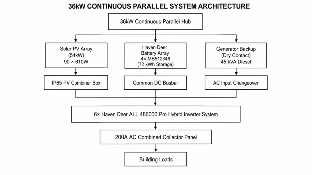
This 36kW microgrid case study details off-grid power engineering for commercial agricultural refrigeration, processing loads, and site autonomy.
7.1 Site System Requirements & Load Profile
- Continuous Operating Load: 28 kW continuous power demand
- Peak Motor Starting Surge: 58 kVA during refrigeration compressor startup
- Daily Energy Throughput: 120 kWh / day
- Location & Solar Exposure: Eastern Europe (4.0 Equivalent Peak Sun Hours)
Paralleling six units absorbs 58 kVA motor surges.
7.2 System Component Specification (Bill of Materials)
| Component Category | Hardware Model / Rating | Quantity | System Design Role |
| Hybrid Inverter Hub | Haven Deer ALL 486000 Pro (6kW / 48V) | 6 Units | Delivers 36kW continuous AC output and handles 72kW surge loads across a unified busbar. |
| Battery Energy Storage | Haven Deer MB512346 Floor-Standing Mobile Cabinet (51.2V 346Ah / 18.0kWh) | 4 Modules | Provides 72.0 kWh total storage (57.6 kWh usable at 80% DoD) on a shared 48V DC bus. |
| Solar PV Modules | Grade A Monocrystalline 610W PV Panel | 90 Panels | Generates 54.9 kW solar input across 12 MPPT channels to power loads and recharge storage. |
| PV Array Combiner | Haven Deer IP65 DC Combiner Box | 6 Units | Protects multi-string PV runs with 32A fuses and 20-40kA Type II SPDs. |
| Auxiliary Backup | 45 kVA Diesel Generator Set | 1 Unit | Auto-starts via Master dry contact relay to recharge batteries during extended solar deficit. |
| AC Combined Panel | 200A Rated Copper Busbar Enclosure | 1 Unit | Combines 6 inverter AC outputs into a unified 200A busbar with main protection. |
7.3 System Operation & Energy Integration Logic
- Daytime Solar Priority (SBU Mode): The 54.9 kW PV array powers site loads directly through the six parallel inverters. Surplus solar generation routes to the 72 kWh LiFePO4 battery array via the central DC busbar.
- Nighttime Battery Autonomy: Four floor-standing MB512346 battery cabinets supply the 28 kW continuous load through the central DC busbar. Operating at 80% DoD yields 57.6 kWh of usable stored energy.
- Automated Generator Integration: When battery SoC drops to 20%, the Master inverter closes its dry contact relay to start the 45 kVA generator. Auto-gen start prevents deep discharge cycles.
8. Frequently Asked Questions (FAQ)
How many hybrid inverters can be connected in parallel on Haven Deer systems?
The ALL 486000 Pro supports up to six units in parallel, scaling single-phase AC output to 36kW. Paralleling scales continuous output linearly.
What happens if one inverter in a parallel cluster encounters a fault?
The Master detects CAN fault flags instantly, isolates the faulty unit, and keeps the remaining parallel array operational.
Do all parallel inverters need to connect to the same battery bank?
Yes. Parallel inverters must connect to a central 48V DC busbar. Equalizing DC input impedance prevents voltage offsets.
Why are matching AC cable lengths mandatory for parallel inverters?
Matched cable lengths equalize branch impedance. Resistance mismatches cause voltage drop variations and uneven load sharing.
Can single-phase hybrid inverters be paralleled to supply three-phase power?
Yes. Assigning inverter clusters to separate phase legs with 120° electrical displacement creates a 400V three-phase system.
What specification of communication cable is required for parallel CAN wiring?
Use double-shielded STP cables (CAT5e/6) with single-point chassis grounding. Shielded twisted pairs eliminate high-frequency PWM noise.
Is a central AC collector box required for paralleling up to 6 units?
Yes. Paralleling requires a central 200A AC collector panel equipped with dedicated branch breakers and Type B RCD protection.
How does the dry contact generator auto-start function work in a parallel system?
The Master unit monitors battery SoC and closes its dry contact relay at 20% SoC. This signal triggers generator auto-start.
Can inverters running different firmware versions be operated in parallel?
No. All parallel units must run identical firmware builds. Mismatched firmware corrupts CAN synchronization.
What is the current sharing imbalance tolerance for Haven Deer parallel inverters?
High-speed CAN control maintains current sharing variance within < 5% across all parallel units at full load.
Does paralleling inverters increase total solar MPPT input capacity?
Yes. Paralleling six ALL 486000 Pro units expands total PV input capacity to 54.9 kW across 12 MPPT channels.
How do I set up DIP switches for a 6-unit parallel system?
Set Unit 1 DIP switches to 1000 (Master) and Slaves 2–6 to 0001–0101. Enable 120 Ω EOL termination resistors on Units 1 and 6 only.
9. Designing a Parallel Microgrid Project?
Deploying a parallel hybrid microgrid within a scalable off-grid solar power system demands precise inverter synchronization, CAN bus validation, balanced busbar sizing, and coordinated protection. Submit site load profiles and system specs to Haven Deer application engineers for single-line diagram (SLD) generation and protection coordination review. Proper SLD validation prevents site commissioning delays.