Quick Definition: A dual AC output hybrid inverter features two independently managed AC ports: Main Output and Smart Load Output. The Main Output backs up critical loads with a 10ms–20ms UPS switchover. During grid outages, the EMS automatically sheds the Smart Load Output to preserve battery capacity.
1. Fundamentals of Dual AC Output Architecture in Hybrid Inverters
Traditional hybrid BESS designs rely on a single AC output circuit for all connected loads. During grid outages, the inverter powers essential equipment and heavy appliances through this shared path. High-draw loads like HVAC units, electric water heaters, and pumps quickly drain battery capacity, shortening runtime for critical systems like refrigeration and communications.
+-----------------------------------------------------------------------------------+
| HYBRID INVERTER DUAL OUTPUT & LOAD DISTRIBUTION TOPOLOGY                          |
+-----------------------------------------------------------------------------------+
|                                                                                   |
|                      ┌───► [Main Output Terminal] ───► [Critical Load Panel]      |
|                      │                                 (Routers, Fridge, Lighting)|
| [Hybrid Inverter] ───┤                                                            |
|  (EMS Controller)    │                                                            |
|                      └───► [Smart Load Terminal]  ───► [Main Distribution Panel]  |
|                                                        (HVAC, Water Heater, Pumps)|
|                                                                                   |
+-----------------------------------------------------------------------------------+
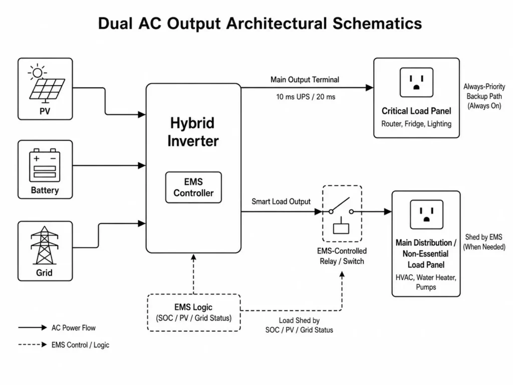
Dual AC output architecture solves this by integrating two independently controlled AC terminals inside the inverter. The internal Energy Management System (EMS) separates essential loads from non-essential loads via dedicated Main Output and Smart Load Output terminals.
1.1 Physical Internal Split: Main Output Terminal vs. Smart Load Output
Dual AC output inverters route power through internal switching circuits and relays to manage distribution between the power stage and both output terminals.
Main Output Terminal: Supplies essential loads directly through the inverter power stage during outages. Haven Deer hybrid inverters deliver a 10ms UPS transfer for sensitive IT loads and a 20ms transfer for general appliances. This port remains energized as long as battery voltage stays above protective limits.
Smart Load Output Terminal: Feeds non-essential loads through an EMS-managed relay. The EMS continuously monitors SOC, battery voltage, PV output, and grid status. When battery capacity drops to the pre-configured threshold during an outage, the EMS opens the relay to shed non-essential loads and preserve backup power for the Main Output.
1.2 The Electrical Problem Resolved by Dual AC Output Systems
Historically, system integrators had to install external contactors, ATS panels, and auxiliary logic devices to separate critical and non-essential loads. This added hardware increased BOM costs, wiring complexity, and installation time.
Haven Deer hybrid inverters—such as the ALL 486000 Pro (6kW single MPPT) and ALL 4812000 Pro (12kW dual MPPT)—embed EMS-based Smart Load control directly inside the chassis.
| Technical Parameter / Feature | Main AC Output Terminal | Smart Load AC Output Terminal |
| Primary Electrical Function | Powers critical loads during utility outages | Powers non-essential loads via EMS load management |
| Transfer Time (Grid to Off-Grid) | 10ms (UPS / IT loads) / 20ms (Standard appliances) | EMS-controlled disconnect/reconnect based on operating parameters |
| Typical Connected Equipment | Routers, servers, refrigerators, security, lighting | HVAC, EV chargers, water heaters, pool pumps |
| EMS Shedding Capability | Stays active until battery low-voltage cutoff | Sheds automatically when SOC hits configured threshold |
| Surge Capacity Support | Supports full inverter surge rating | Restricted to remaining inverter headroom |
| Wiring Destination | Dedicated critical load sub-panel | Main distribution panel or non-essential sub-panel |
For more on advanced off-grid features, check out our The Architecture of Modern Off-Grid Solar ESS Kits: Engineering Multi-Source Resilience.
2. Main Output Engineering: Guaranteeing 10ms UPS Continuity for Critical Loads
The Main Output terminal keeps mission-critical loads energized during utility outages. Sensitive hardware—such as IT servers, routers, and medical devices—demands sub-cycle transfer times to prevent system reboots and data loss.
2.1 Critical Load Panel Sizing & Power Budgeting
Designers must calculate total continuous demand and inrush surge current before landing circuits on the Main Output sub-panel. Total load must not exceed the inverter’s rated continuous AC output.
To calculate the maximum permissible load on the Main Output:
P_Main_Total = Σ P_Continuous + max(P_Surge_Peak) ≤ P_Inverter_Continuous_Rating
Where:
P_Main_Total = Total anticipated power demand on the Main Output terminal (kW)
Σ P_Continuous = Sum of all continuous load running power values (kW)
max(P_Surge_Peak) = Highest single inductive motor startup surge demand (kW) P_Inverter_Continuous_Rating = Rated continuous AC output power of the inverter (kW)
Worked Example: A residential system uses the Haven Deer ALL 4812000 Pro with 12kW continuous output and 22kVA surge capacity for 5 seconds. The critical load panel includes:
- Router & Network Switch: 100W
- Refrigeration & Deep Freezers: 800W
- running (3,000W peak surge) LED Lighting Circuits: 400W
- Security System & Cameras: 200W
- High-Performance Workstation: 500W
Σ P_Continuous = 100W + 800W + 400W + 200W + 500W = 2,000W (2.0 kW)
max(P_Surge_Peak) = 3,000W (3.0 kW)
P_Main_Total = 2.0 kW + 3.0 kW = 5.0 kW
The 5.0 kW total demand sits comfortably inside the inverter’s 12kW continuous rating and 22kVA surge ceiling.
2.2 Transfer Dynamics (10ms UPS vs 20ms Appliance Switching)
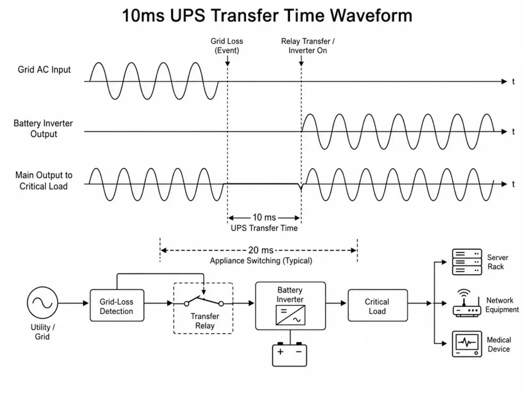
Upon grid failure, the inverter detects out-of-spec voltage or frequency and shifts the load to the battery power stage. An onboard DSP triggers the transfer relay and drives the DC-to-AC stage from the 48V LFP bank.
+----------------------------------------------------------------------------------------------------+
| GRID LOSS DETECTION & AUTOMATIC RELAY TRANSFER FLOW                                                |
+----------------------------------------------------------------------------------------------------+
|                                                                                                    |
|  Grid Power (Normal) ──┐                                                                           |
|                        ├──► [Grid Loss Detection] ──► [Relay Transfer] ──► [Battery Inverter Output]  |
|  Battery DC Power ─────┘                                                                           |
|                                                                                                    |
+----------------------------------------------------------------------------------------------------+
- 10ms Transfer Speed: Protects sensitive IT gear, servers, and routers without triggering power supply resets during grid drops.
- 20ms Transfer Speed: Powers standard household loads where brief voltage interruptions will not disrupt operation.
Engineering Tip (Inductive Motor Surges): Compressor motors and water pumps draw inrush currents up to 3–5x their rated running power. Keep the largest motor surge under the inverter’s peak kVA limit, or offload heavy motors to the Smart Load terminal.
3. Smart Load Output Engineering: Automated Load Shedding Logic & Controls
Firmware-embedded EMS control drives the Smart Load Output. During utility outages, it sheds non-essential consumption to reserve battery capacity for critical loads.
3.1 EMS Control Triggers: SOC % vs. Battery Cutoff Voltage
Installers can configure Smart Load disconnection triggers using two operating metrics:
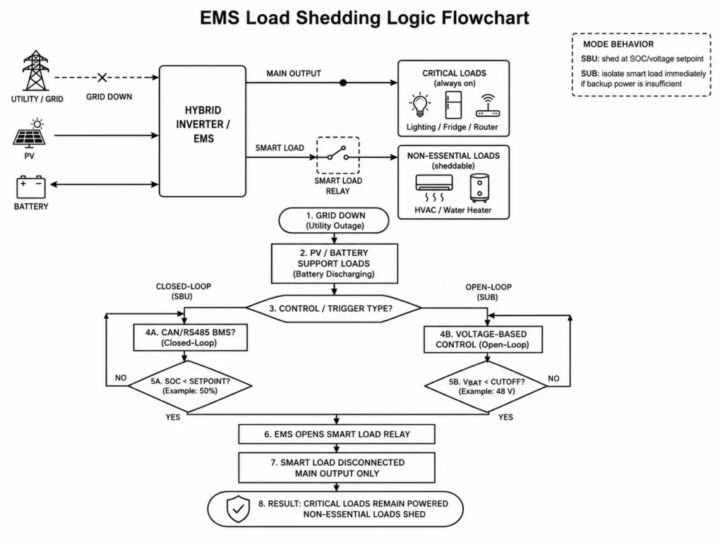
State of Charge (SOC %) Shedding: Ideal for systems utilizing closed-loop CAN/RS485 BMS communications protocol architectures. The BMS sends real-time SOC data to the EMS, triggering load shedding at pre-set SOC cutoffs.
Voltage-Based Shedding: Required for open-loop battery setups. The EMS opens the Smart Load relay when pack voltage hits the low-voltage cutoff threshold under load.
+-----------------------------------------------------------------------------------+
| GRID DISCONNECT & SMART LOAD SHEDDING FLOW                                        |
+-----------------------------------------------------------------------------------+
|                                                                                   |
|                                   [Grid Down]                                     |
|                                        │                                          |
|                                        ▼                                          |
|                              [Battery Discharging]                                |
|                                        │                                          |
|                                        ▼                                          |
|                                 [SOC Drops < 50%]                                 |
|                                        │                                          |
|                                        ▼                                          |
|                           [EMS Opens Smart Load Relay]                            |
|                                        │                                          |
|                                        ▼                                          |
|                                [Main Output Only]                                 |
|                                                                                   |
+-----------------------------------------------------------------------------------+
3.2 Operating Modes Behavior: SBU vs. SUB Load Shedding Profiles
The Smart Load terminal coordinates directly with the inverter’s energy priority modes:
SBU Mode (Solar → Battery → Utility): Prioritizes self-consumption. During grid outages, PV and battery feed both ports until SOC drops to the shedding setpoint, forcing the EMS to drop the Smart Load and protect the Main Output.
SUB Mode (Solar → Utility → Battery): Reserves battery capacity strictly for backup. If grid power drops and combined PV/battery output cannot support total demand, the EMS isolates the Smart Load terminal immediately.
To see how EMS handles energy inputs, check out our How Integrated EMS Coordinates PV, Battery, Grid & Generator: Architecture & Control Logic.
To calculate emergency autonomy when operating with UL 1973-certified stationary battery packs, apply the formula:
T_Autonomy = (E_Battery × DoD × η_Inverter) / P_Main_Load
Where:
T_Autonomy = Battery autonomy time (hours)
E_Battery = Total nominal battery storage capacity (kWh)
DoD = Depth of Discharge ratio used for calculation (decimal, e.g., 0.80 for 80% DoD)
η_Inverter = Battery-to-AC conversion efficiency of the inverter (decimal)
P_Main_Load = Continuous power demand of the critical load panel (kW)
Common Installation Mistake: Landing heavy inductive loads (like HVAC or water heaters) on the Main Output sub-panel instead of the Smart Load terminal. During an outage, these high-draw loads rapidly deplete the battery and collapse backup runtime for critical circuits.
| Battery Storage Configuration (51.2V Grade A LiFePO₄) | Total Combined Load (Main + Smart Load) | Critical Load Only (Main Output Panel) | Battery Autonomy WITHOUT Shedding (Full Load) | Battery Autonomy WITH Smart Load Shedding | Total Runtime Extension (%) |
| 5.12 kWh (1 × AL-WM512100) | 2.5 kW | 0.5 kW | ~1.5 Hours | ~7.6 Hours | +406% |
| 10.24 kWh (1 × AL-WM512200) | 4.0 kW | 1.0 kW | ~2.1 Hours | ~8.4 Hours | +300% |
| 15.00 kWh (1 × MB512300 Mobile Cabinet) | 5.0 kW | 1.2 kW | ~2.5 Hours | ~10.4 Hours | +316% |
| 30.72 kWh (6 × AL-WM512100 Parallel Bank) | 8.0 kW | 2.0 kW | ~3.2 Hours | ~12.8 Hours | +300% |
4. Wiring Topologies and Single-Line Diagram (SLD) Implementation
Installing a dual AC output inverter requires isolating line and neutral conductors between the Main Output critical load panel and Smart Load circuits.
+-----------------------------------------------------------------------------------+
| HYBRID INVERTER AC INTERFACE & THREE-TERMINAL TOPOLOGY                            |
+-----------------------------------------------------------------------------------+
|                                                                                   |
|                      ┌───► [Main Output AC Line] ───► [Critical Load Sub-Panel]   |
|                      │                                (Dedicated Neutral Bus)     |
|  [Hybrid Inverter] ──┼───► [AC Input Terminal]   ◄─── [Grid / Generator]          |
|                      │                                                            |
|                      └───► [Smart Load AC Line]  ───► [Non-Essential Load Panel]  |
|                                                       (HVAC, Pumps, Water Heater) |
|                                                                                   |
+-----------------------------------------------------------------------------------+
4.1 Sub-panel Separation: Critical Load Sub-Panel vs. Main Household Panel
Installers must route output circuits through two distinct distribution panels:
Main Distribution Panel (Non-Essential Loads): Feeds non-essential loads like HVAC, water heaters, and EV chargers. Connect the Smart Load Output through a dedicated breaker to this panel or a non-essential sub-panel.
Critical Load Sub-Panel: Installs downstream from the inverter Main Output to power essential circuits. Land all critical load neutral conductors on the dedicated, isolated neutral bus inside this sub-panel.
Safety & Standards Note (Neutral Line Isolation): Never bridge the Critical Load sub-panel neutral bus with the Smart Load or grid neutral downstream of the inverter. Shared neutrals trigger ground-fault trip errors, disrupt inverter protections, and violate IEC 60364 low-voltage standards.
4.2 Overcurrent Protection & Circuit Breaker Sizing Standards
Size all AC output conductors for maximum continuous current, and protect each circuit with an appropriately rated thermal-magnetic breaker.
To estimate the required AC conductor cross-sectional area based on allowable voltage drop:
ΔV = (2 × L × I × ρ) / A ≤ 1.5% × 230V
Where:
ΔV = Calculated voltage drop across the AC conductor (V)
L = One-way conductor length (meters)
I = Continuous maximum AC current (Amperes)
ρ = Copper conductor resistivity (0.0175 Ω·mm²/m at 20°C)
A = Conductor cross-sectional area (mm²)
| Inverter Model | Rated Continuous AC Output Power | Rated Continuous AC Output Current (230V) | Recommended Main Output AC Breaker | Recommended Smart Load AC Breaker | Recommended Minimum Copper Wire Cross-Section |
| ALL 486000 Pro (6kW Single MPPT) | 6,000 W | 26.1 A | 32A 2-Pole MCB | 32A 2-Pole MCB | 6.0 mm² (10 AWG) |
| ALL 4812000 Pro (12kW Dual MPPT) | 12,000 W | 52.2 A | 63A 2-Pole MCB | 63A 2-Pole MCB | 16.0 mm² (6 AWG) |
Pre-Powering Verification Checklist for Installers
- Verify that line and neutral conductors from the Main Output terminal route exclusively to the Critical Load Sub-Panel.
- Confirm zero physical connection between the Main Output neutral bus and Smart Load neutral bus downstream of the inverter.
- Match circuit breaker continuous ratings directly to wire gauge ampacity (e.g., 32A breaker for 6.0 mm² copper wire).
- Verify PE grounding connections between the inverter chassis and site grounding electrode per IEC 62109-1 requirements.
5. Integrating Auxiliary Inputs: Dual Output Coordination with Generators & PV
Modern hybrid systems integrate PV, battery, and generator inputs into a unified microgrid. The EMS dynamically coordinates Main Output and Smart Load terminals based on live PV yield, battery SOC, and generator status.
+-----------------------------------------------------------------------------------+
| HYBRID INVERTER MULTI-SOURCE INPUT & DUAL OUTPUT TOPOLOGY                         |
+-----------------------------------------------------------------------------------+
|                                                                                   |
|  [Solar PV Array] ──────┐                                                         |
|                         │                                                         |
|  [AC Generator] ────────┼──► [Hybrid Inverter / EMS Hub] ───► [Main Output]       |
|  (via Dry Contact)      │                                └──► [Smart Load]        |
|                         │                                                         |
|  [LiFePO₄ Battery] ─────┘                                                         |
|                                                                                   |
+-----------------------------------------------------------------------------------+
5.1 Dry Contact Relay Triggering During Smart Load Shedding
When PV output drops and battery SOC reaches the shedding threshold, the EMS drops the Smart Load. If battery capacity continues to fall, the inverter closes an onboard dry contact relay to auto-start an external generator.
Start Sequence: When SOC or pack voltage hits the generator start setpoint, the dry contact relay closes, signaling the generator’s remote start controller to fire up.
Load Dispatch Strategy: Once generator voltage and frequency stabilize, the inverter accepts AC input to power loads and recharge the battery bank. The EMS re-energizes the Smart Load port as total power headroom expands.
Hardware Operating Constraint: The inverter shares a single AC input port between utility grid and generator feeds. Never connect grid and generator lines simultaneously without an external transfer switch compliant with IEEE 1547 grid interconnection standards.
Learn more about automated generator integration in our Automated Generator Integration via Passive Dry Contact: Engineering Architecture & Configuration Guide.
5.2 Surplus PV Routing to Smart Load Terminals
Under peak solar irradiance, the ALL 4812000 Pro’s dual MPPT channels (supporting up to 15,000W PV input) often produce more power than critical loads and battery charging demand combined.
The EMS routes this surplus solar power directly to the Smart Load terminal, maximizing self-consumption by running dump loads like water heaters or irrigation pumps.
| System Operating Scenario | Utility Grid | Solar PV Generation | Battery State of Charge (SOC) | Main Output Status | Smart Load Output Status | Auxiliary Generator Relay Signal |
| Grid Online (Normal) | Available | Any Level | Any Level | ON (Grid Bypass) | ON (Grid Supply) | Open (Inactive) |
| Grid Outage (High SOC) | Offline | Moderate / High | > 50% SOC | ON (Inverter UPS) | ON (PV + Battery Supply) | Open (Inactive) |
| Grid Outage (Low SOC) | Offline | Low / Zero | < 50% SOC | ON (Inverter UPS) | OFF (Shed by EMS) | Open (Inactive) |
| Grid Outage (Critical SOC) | Offline | Zero | < 20% SOC | ON (Inverter UPS) | OFF (Shed by EMS) | CLOSED (Trigger Generator Start) |
| Generator Running | Offline | Any Level | Recharging | ON (Generator Supplied) | ON (Generator Supplied) | Closed (Active) |
6. Common Installation Mistakes & System Design Pitfalls
Flawed dual AC output wiring causes inverter fault trips, shortened backup runtime, and system instability. Commissioning engineers must verify and resolve these four common installation pitfalls:
1. Interconnecting Neutral Conductors (Shared Neutral Error)
- Root Cause: Connecting the Main Output neutral to the Smart Load or grid neutral bus.
- System Impact: Neutral loops trigger ground-fault errors, corrupt current sensing, and trip inverter safety relays.
- Remedial Action: Isolate Main Output neutrals onto the Critical Load Sub-Panel’s dedicated neutral bus.
2. Overloading Main Output with High-Surge Inductive Loads
- Root Cause: Landing compressors or heavy pumps directly on the Main Output sub-panel.
- System Impact: Inrush current causes severe AC voltage sags, crashing sensitive IT gear on the critical bus.
- Remedial Action: Shift high-draw motor loads to the Smart Load terminal, or install soft starters.
3. Misconfiguring EMS Battery Shedding Thresholds
- Root Cause: Setting the Smart Load shedding SOC cutoff too low in EMS settings.
- System Impact: Non-essential loads drain the battery bank prematurely, collapsing emergency backup duration for critical circuits.
- Remedial Action: Set the shedding threshold to preserve at least 40%–50% SOC exclusively for the Main Output.
4. Undersizing Output Circuit Breakers for Parallel Operations
- Root Cause: Sizing AC breakers for a single inverter unit in a multi-inverter parallel stack.
- System Impact: Main breakers nuisance-trip during peak generation when parallel units export to the shared bus.
- Remedial Action: Size breakers and busbars for total combined parallel output current per local electrical codes.
+-----------------------------------------------------------------------------------+
| ELECTRICAL SYSTEM TROUBLESHOOTING & EMS OPTIMIZATION LOGIC                        |
+-----------------------------------------------------------------------------------+
|                                                                                   |
|  SCENARIO 1: NEUTRAL BUS ISOLATION                                                |
|  [Shared Neutral Connection]                                                      |
|        │                                                                          |
|        ▼                                                                          |
|  [Abnormal Current Path]                                                          |
|        │                                                                          |
|        ▼                                                                          |
|  [Solution: Separate Neutral Buses]                                               |
|                                                                                   |
|  SCENARIO 2: MOTOR LOAD MANAGEMENT                                                |
|  [Heavy Motor on Main Output]                                                     |
|        │                                                                          |
|        ▼                                                                          |
|  [Voltage Drop Risk]                                                              |
|        │                                                                          |
|        ▼                                                                          |
|  [Solution: Move Non-Essential Motors to Smart Load]                             |
|                                                                                   |
|  SCENARIO 3: BACKUP DURATION OPTIMIZATION                                         |
|  [Low Smart Load Threshold]                                                       |
|        │                                                                          |
|        ▼                                                                          |
|  [Reduced Backup Duration]                                                        |
|        │                                                                          |
|        ▼                                                                          |
|  [Solution: Adjust EMS Shedding Settings]                                         |
|                                                                                   |
+-----------------------------------------------------------------------------------+
7. Technical FAQs: Dual AC Output Engineering
What is a dual AC output hybrid inverter?
A dual AC output hybrid inverter houses two separately controlled AC terminals: Main Output for critical loads and Smart Load Output for non-essential loads. During utility outages, the EMS sheds the Smart Load terminal to protect battery runtime for critical equipment.
How does the inverter decide when to turn off the Smart Load output?
The internal EMS continuously monitors pack SOC, terminal voltage, and PV input. When utility power fails and battery capacity hits the programmed cutoff threshold, the EMS opens the internal relay to isolate the Smart Load.
Can I run heavy motor loads like air conditioners on the Main Output?
While the Main Output handles motor inrush surges, heavy inductive loads like HVAC and pumps belong on the Smart Load terminal. This prevents rapid battery drain during prolonged outages.
What is the transfer time of the Main AC Output when utility power fails?
Haven Deer inverters switch to battery backup in 10ms for sensitive IT hardware and 20ms for standard appliances, preventing equipment reboots during grid drops.
Is a separate sub-panel required for installing a dual AC output inverter?
Yes. You must wire critical loads to a dedicated sub-panel fed by the Main Output. Non-essential branch circuits connect to the main distribution panel fed by the Smart Load port.
Does the Smart Load turn back on automatically when solar power returns?
Yes. Once PV array power, grid voltage, or generator input recovers above the programmed threshold, the EMS automatically closes the relay to re-energize the Smart Load terminal.
Can an AC backup generator supply power through a dual output inverter?
Yes. Connect the generator output to the inverter’s AC input port. Once running, the generator powers both AC output ports and recharges the battery bank based on EMS charging limits.
What happens if I connect both outputs to the same neutral bar?
Tying Main Output and Smart Load neutrals together creates ground loops, trips inverter protection relays, and violates IEC 60364 wiring standards.
How does dual AC output differ from a single AC output inverter with an external ATS?
Dual AC output embeds load-shedding control directly into inverter firmware and internal relays. This eliminates external contactors, ATS panels, and auxiliary control logic.
Which Haven Deer inverter models support dual AC output functionality?
The Haven Deer ALL 486000 Pro (6kW single MPPT) and ALL 4812000 Pro (12kW dual MPPT) feature integrated dual AC output ports with programmable EMS load-shedding control.
8. System Engineering & SLD Design Support
Haven Deer delivers direct engineering support for system integrators, EPC contractors, and distributors. Our application team assists with system topology design, hardware selection, and EMS control strategies.
Contact our application engineering team to receive site-specific Single-Line Diagrams (SLDs), protection device sizing schedules, or tailored EMS load-shedding parameters.
Engineering Consultation: Request Your Site-Specific SLD & System Design Review