Quick Summary: When evaluating open-loop vs. closed-loop BMS configurations, the key difference is communication. A closed-loop BMS connects to a hybrid inverter via CAN or RS485, exchanging real-time SoC, cell temperatures, and dynamic charge/discharge limits. In contrast, an open-loop setup relies solely on the inverter’s DC terminal voltage to estimate pack status. Because LiFePO4 has a flat discharge curve, voltage-only tracking is unreliable, leading to SoC drift, premature low-voltage cutoffs, and lost usable capacity.
1. Fundamental Architecture: How Inverters & Batteries Share Operational Telemetry
Modern off-grid solar power system architecture splits system operations into two distinct layers: power and data. The power path routes high-current energy across PV arrays, battery packs, and the inverter DC bus. The data path enforces operational logic and safety cutoffs.
As the central energy hub, the hybrid inverter governs these limits through either open-loop or closed-loop architecture.
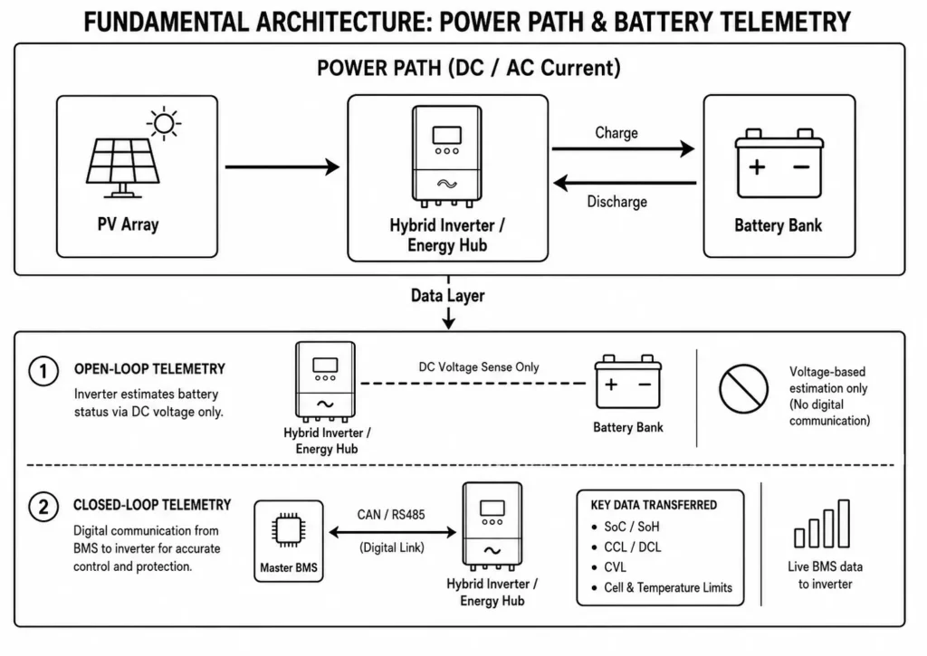
1.1 Open-Loop Topology (Voltage-Based Estimation)
Open-loop architectures lack a digital comms link between the BMS and inverter EMS. The inverter treats the pack as a generic DC source, operating without internal BMS telemetry.
To regulate charge cycles, the inverter reads terminal DC voltage against hardcoded thresholds like bulk, float, and low-DC cutoffs. Internal lookup tables estimate battery status. Voltage-only regulation creates blind spots.
1.2 Closed-Loop Topology (Protocol-Driven Automation)
Closed-loop systems connect the master BMS to the inverter via a dedicated comms bus, typically CAN or RS485 Modbus.
Instead of guessing status from voltage, the inverter receives live digital telemetry from the BMS. The BMS dynamically broadcasts critical protection thresholds:
- Cell-level SoC and SoH
- Real-time Charge Current Limit (CCL) and Discharge Current Limit (DCL)
- Real-time Charge Voltage Limit (CVL)
- Cell voltage extremes and temperature extremes
Dynamic telemetry prevents overcharging and thermal stress.
2. Engineering Comparison: Open-Loop vs. Closed-Loop BMS Control Logic
Closed-loop control replaces crude voltage estimates with active, cell-level BMS telemetry. System designers calculate usable battery energy using:
Eusable = Vpack × Ah × DoD
Where:
Eusable = Usable battery energy output (kWh)
Vpack = Nominal battery pack voltage (51.2V DC for a standard 16S LiFePO4 configuration)
Ah = Rated amp-hour capacity
DoD = Depth of Discharge (expressed as a decimal)
Open-loop installs force integrators to cap practical DoD at 70%–80% to avoid unexpected low-voltage cutoffs during load spikes. Closed-loop setups safely unlock full rated DoD by tracking true pack limits in real time. Closed-loop control maximizes usable capacity.
2.1 State-of-Charge (SOC) Precision & The LFP Flat Voltage Curve
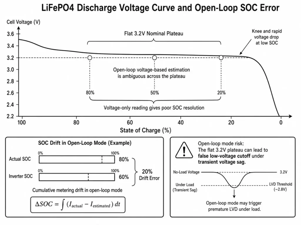
LiFePO4 chemistry maintains a flat voltage discharge curve across 20%–90% SoC, lingering around 51.2V DC under nominal loads.
Within this plateau, a 0.2V drop can span a 30% capacity delta. Open-loop inverters cannot resolve SoC from voltage alone. Voltage tracking fails on LFP plateaus.
Closed-loop BMS integration combines coulomb counting and cell monitoring to deliver true SoC tracking.
2.2 Dynamic Current & Voltage Throttling (CCL & CVL Execution)
Open-loop inverters push fixed charging profiles without cell-level feedback from the BMS.
In closed-loop mode, if a single cell in a 16S string spikes toward its upper voltage limit, the BMS throttles the inverter instantly via CAN bus CCL/CVL commands.
The inverter scales back charge current immediately, preventing over-voltage trips while passive balancing catches up.
2.3 Thermal Safeguards & Multi-Layer Fault Escalation
Charging LFP cells near or below 0°C causes lithium plating and cell damage.
Closed-loop sensors send real-time thermistor readings to the BMS. Near 0°C, the BMS sets CCL to 0A, forcing the inverter to halt charge current while continuing to serve loads from PV or grid. Temperature gating prevents cell damage.
Open-loop systems lack thermal telemetry and cannot respond to localized thermal events.
| Engineering Parameter | Open-Loop Control (Voltage-Based) | Closed-Loop Control (Protocol-Driven) |
| Data Interface | Hardwired DC voltage sensing only | CAN 2.0B / RS485 digital bus |
| SOC Calculation | Terminal voltage lookup tables | BMS coulomb counting & cell monitoring |
| SOC Precision | Poor (±15–20% drift on LFP plateau) | High (±2–3% via BMS telemetry) |
| Current Throttling | Static inverter parameters | Dynamic BMS commands (CCL/DCL) |
| Voltage Control | Fixed profile (Bulk/Float) | Dynamic cell-guided CVL |
| Thermal Protection | Inverter ambient sensor only | Direct cell-level thermistor feedback |
| Parallel Management | Uncoordinated parallel strings | Master BMS telemetry aggregation |
| Usable DoD Range | Capped at 70%–80% for safety | 90%–95% designed range unlocked |
Engineering Tip: Closed-loop communication provides active system protection. By dynamically adjusting CCL based on live cell voltage and temperature, the BMS eliminates nuisance trips and prevents premature degradation.
3. Technical Risks of Operating LiFePO₄ Batteries in Open-Loop Mode
Running Grade A LiFePO4 packs in open-loop mode introduces severe SoC tracking drift and false low-voltage cutoffs. Open-loop operation risks cumulative metering drift.
3.1 SOC Cumulative Drift & Battery Metering Discrepancies
Without BMS calibration signals, inverter current-sensor offsets accumulate over time during charge and discharge cycles.
A simplified model for cumulative SOC estimation error is:
ΔSOC = ∫ (Iactual – Iestimated) dt
Where:
ΔSOC = Accumulated State-of-Charge estimation error (%)
Iactual = Actual current passing through the battery cells
Iestimated = Current measured by the inverter control system
dt = Operational time interval
Over extended cycling, uncalibrated current integration causes displayed SoC to drift drastically from actual battery state. Uncalibrated coulomb counting corrupts SoC tracking.
3.2 Premature Low-Voltage Cutoff & Unusable Capacity Lock-Out
High-current surges—such as a 12kW inverter starting motor loads—pull heavy DC current, dropping voltage across internal cell resistance, busbars, and cables:
V = I × R
Open-loop inverters mistake this temporary voltage sag for a fully discharged pack, triggering premature Low-Voltage Disconnect (LVD). Transient voltage sags cause nuisance LVD shutdowns.
In closed-loop systems, cell-level telemetry enables the inverter to distinguish between temporary voltage sags under load and true low-capacity states.
Common Mistake: Setting LVD cutoffs too high on 51.2V LFP banks triggers false shutdowns under load spikes. Voltage sags across cable runs and internal DC resistance trick the inverter into reading a dead battery.
4. Protocol Engineering: CAN Bus vs. RS485 Industrial Communication
Closed-loop reliability depends directly on bus topology and protocol selection. CAN Bus and RS485 serve as the standard differential interfaces across commercial and residential BESS.
+-----------------------------------------------------------------------------------+
| INVERTER EMS TO MASTER BMS CAN BUS PHYSICAL INTERFACE                             |
+-----------------------------------------------------------------------------------+
|                                                                                   |
|  +----------+       CAN-H  ==========================  CAN-H       +----------+   |
|  | Inverter |                                                      |  Master  |   |
|  | EMS      |       CAN-L  ==========================  CAN-L       |   BMS    |   |
|  +----------+                                                      +----------+   |
|                                                                                   |
+-----------------------------------------------------------------------------------+
+-----------------------------------------------------------------------------------+
| MASTER INVERTER TO SLAVE BMS RS485 PHYSICAL INTERFACE                             |
+-----------------------------------------------------------------------------------+
|                                                                                   |
|  +----------+       RS485-A ------------------------ RS485-A       +----------+   |
|  | Master   |                                                      |  Slave   |   |
|  | Inverter |       RS485-B ------------------------ RS485-B       |   BMS    |   |
|  +----------+                                                      +----------+   |
|                                                                                   |
+-----------------------------------------------------------------------------------+
4.1 Controller Area Network (CAN): Differential High-Speed Bus Telemetry
CAN Bus (typically CAN 2.0B at 250kbps or 500kbps) provides the primary inverter-to-BMS comms link.
- Differential Voltage Signaling: CAN-High and CAN-Low lines transmit inverse differential voltages. Transceivers read differential potential, rejecting high-frequency noise from inverter switching circuits. Differential signaling rejects switching noise.
- Hardware Arbitration: Built-in message ID prioritization guarantees high-priority alarm frames preempt standard status telemetry without frame collisions.
4.2 RS485 Modbus RTU: Master-Slave Multi-Drop Data Exchange
RS485 operates as a differential half-duplex interface running Modbus RTU over serial line protocols via shielded twisted pair. Under master-slave polling, the inverter queries specific battery Modbus slave IDs sequentially.
While slower than CAN (9.6–19.2 kbps vs 250–500 kbps), RS485 handles longer cable runs. Integrators primarily use RS485 for intra-pack communications between parallel battery modules. Master-slave polling creates telemetry latency.
4.3 Multi-Pack Telemetry Aggregation via Master-Slave BMS
Parallel battery banks must never flood the inverter with competing CAN streams.
Integrators set hardware DIP switches to designate one pack as Master BMS and remaining packs as Slaves with unique IDs. Slaves report internal pack telemetry to the Master via RS485. The Master aggregates total Ah, worst-case cell voltages, and thermal extremes into a single CAN stream sent to the inverter. Aggregated telemetry prevents CAN bus collisions.
| Technical Parameter | CAN Bus Protocol (CAN 2.0B) | RS485 Protocol (Modbus RTU) |
| Physical Architecture | Differential Multi-Master | Differential Master-Slave |
| Standard Bus Speed | 250 kbps / 500 kbps | 9.6 kbps / 19.2 kbps |
| Noise Immunity (EMI) | High | High with proper shielding |
| Collision Handling | Hardware message arbitration | Software timeout and retry |
| Primary System Function | Inverter-to-Master BMS Link | Intra-pack module telemetry |
Engineering Tip: Install 120 Ω termination resistors at both physical ends of the CAN/RS485 bus. Proper termination prevents signal reflection, signal corruption, and bus-off errors across long cable runs.
5. Co-Engineered Closed-Loop System Architecture: Haven Deer Ecosystem Integration
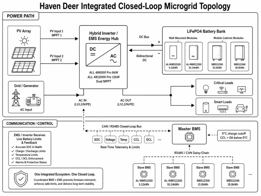
Long-term stability requires firmware alignment between the hybrid inverter and battery BMS. Haven Deer integrates hybrid inverters, Grade A LiFePO4 modules, and layered BMS/EMS logic into a single ecosystem. Integrated control prevents firmware mismatch.
5.1 Hybrid Inverter Energy Hub Control Interface
Haven Deer hybrid solar inverters—including the ALL 486000 Pro (6kW) and ALL 4812000 Pro (12kW dual-MPPT)—act as energy hubs with native CAN and RS485 comms.
At boot, the inverter EMS negotiates closed-loop comms over CAN or RS485. After the handshake, the inverter ingests live parameters and current limits from the Master BMS:
- ALL 486000 Pro: Handles up to 9000W PV input, dynamically throttling charge power based on live BMS telemetry.
- ALL 4812000 Pro: Pairs dual independent MPPTs (60–500V DC) with a 160A solar charger, aligning high-current output with BMS-issued CCL commands.
5.2 Industrial LiFePO₄ Battery Pack Protocols
Haven Deer storage hardware—from wall-mounted home solar batteries (AL-WM512100 5.12kWh, AL-WM512200 10.24kWh) to mobile off-grid solar batteries (MB512300 15.0kWh, MB512346 18.0kWh)—pairs Grade A prismatic LiFePO4 cells with multi-protocol BMS controllers.
- Multi-Protocol Native Bus: Ships with pre-flashed CAN and RS485 protocol libraries for direct inverter integration.
- Multi-Layer Cell Safety: Manages individual cell balancing and enforces thermal protection, dropping CCL to 0A below 0°C to prevent lithium plating. Hardware gating protects pack integrity.
6. Installer Field Protocol: Commissioning Closed-Loop BMS Communication
Commissioning closed-loop BESS comms requires a disciplined physical and protocol setup sequence. Execution errors trigger comms faults.
+-----------------------------------------------------------------------------------+
| SYSTEM COMMISSIONING & PROTOCOL CONFIGURATION FLOW                                |
+-----------------------------------------------------------------------------------+
|                                                                                   |
| [Assign BMS Addresses]                                                            |
|        │                                                                          |
|        ▼                                                                          |
| [Connect Communication Wiring]                                                    |
|        │                                                                          |
|        ▼                                                                          |
| [Power On Battery System]                                                         |
|        │                                                                          |
|        ▼                                                                          |
| [Configure Inverter Protocol]                                                     |
|        │                                                                          |
|        ▼                                                                          |
| [Verify Communication Status]                                                     |
|                                                                                   |
+-----------------------------------------------------------------------------------+
6.1 Hardware Interfacing, DIP Address Assignment & Pinout Mapping
- Power Isolation: Open the main DC circuit breaker between the battery bank and inverter before plugging in comms cables or setting DIP switches.
- Assign DIP Switches: Set hardware DIP switches prior to powering on. Assign ID 1 (or 0) to the Master BMS and unique sequential IDs (2, 3, 4…) to slave packs. Duplicate IDs crash the comms bus.
- Verify Pinout Mapping: Cross-check cable pinouts against manufacturer schematics. Never assume standard RJ45 Ethernet patch cables match inverter CAN-H/CAN-L or RS485-A/RS485-B pin assignments.
- Connect Communication Cabling: Daisy-chain internal slave-to-slave comms via RS485. Run the primary CAN cable from the Master BMS port directly to the designated inverter BMS port.
6.2 Verification Checklist & Resolving Protocol Alarm Faults
Run this commissioning checklist before first-time system energization:
- [ ] Hardware DIP switch addresses assigned without duplicate IDs.
- [ ] Comms cables plugged into designated BMS/CAN ports, not standard Ethernet LAN ports.
- [ ] Outdoor-rated shielded twisted pair (STP) installed near high-power AC/DC lines to mitigate EMI.
- [ ] Master BMS actively communicating with all connected slave packs.
- [ ] Inverter protocol setting matched to the specific battery CAN/RS485 profile.
| Alarm / Fault Code | Root Cause | Engineering Resolution |
| BMS Communication Fault / Error Code | Disconnected cable or incorrect pinout configuration | Verify RJ45 crimps; confirm CAN-H/CAN-L or RS485-A/B pin alignment at both ends. |
| Communication Protocol Mismatch | Incorrect battery protocol selected in inverter settings | Select the exact battery manufacturer protocol profile in the inverter configuration menu. |
| Battery Address Conflict | Duplicate DIP switch addresses assigned to parallel packs | Power down DC bus; assign unique sequential DIP switch IDs to each slave pack. |
| Communication Data Loss | High EMI noise or unshielded cabling runs | Replace with shielded twisted pair (STP); route comms lines away from AC power conductors. |
7. Frequently Asked Questions
What is the main difference between open-loop and closed-loop BMS communication?
Open-loop relies mainly on the hybrid inverter measuring DC terminal voltage and using predefined parameters to estimate battery status. Closed-loop uses digital communication protocols such as CAN or RS485 to exchange battery SOC, temperature information, and dynamic charge/discharge limits between the BMS and inverter.
Why is voltage-based SOC estimation inaccurate for LiFePO₄ batteries?
LiFePO₄ cell chemistry features a relatively flat voltage discharge region across a wide SOC range. Small voltage variations caused by load changes can make SOC estimation less accurate when relying only on voltage-based lookup tables.
Can Haven Deer Hybrid Inverters operate in open-loop mode?
Yes. Haven Deer inverters run open-loop using manual terminal voltage setpoints for legacy retrofits. However, closed-loop CAN/RS485 integration is required to unlock full capacity and prevent nuisance trips. Closed-loop control is strongly recommended.
What protocols do Haven Deer batteries use for closed-loop control?
Haven Deer AL-WM wall-mounted batteries and MB Floor-standing Mobile Cabinet Batteries utilize intelligent BMS controllers supporting CAN, RS485, and RS232 communication interfaces for integration with compatible hybrid inverters.
How does closed-loop communication prevent low-temperature charging damage?
At 0°C, the BMS sets CCL to 0A over CAN bus, forcing the inverter to halt charge current instantly to prevent lithium plating. Load-serving from PV or grid continues uninterrupted. Zero-current gating prevents permanent cell damage.
What are CCL and CVL in closed-loop systems?
Charge Current Limit (CCL) and Charge Voltage Limit (CVL) are battery protection parameters provided by the BMS and used by the inverter to adjust charging power according to cell voltage and temperature conditions.
How many battery packs can communicate in parallel under closed-loop control?
Haven Deer Master-Slave BMS architecture aggregates up to 6 parallel packs by default—or 16 via DIP switch configuration—reporting the total array to the inverter as a single virtual pack.
What happens if the communication cable between BMS and Inverter is disconnected?
When comms drop, the inverter watchdog timer triggers a BMS Comms Fault code within seconds. The inverter gracefully ramps down charge/discharge current or halts to prevent thermal runaways. Comms loss triggers immediate fault isolation.
Do I need external termination resistors for CAN/RS485 closed-loop wiring?
Short communication links between compatible equipment may use internal termination settings. For longer cable runs or multi-device communication networks, appropriate 120 Ω termination resistors should be installed according to the communication topology requirements.
Does closed-loop communication increase usable battery capacity?
Yes. By improving battery status monitoring, reducing unnecessary voltage-based shutdowns, and supporting coordinated cell protection, closed-loop control can improve usable battery capacity and system reliability.
8. Engineering Your Closed-Loop Solar ESS Integration
Eliminate SoC estimation drift, false low-voltage disconnects, and premature degradation across any commercial or residential off-grid solar power system. Closed-loop control protects system ROI.
Work directly with Haven Deer application engineers to deploy pre-configured hybrid inverters and Grade A LiFePO4 battery banks backed by native CAN/RS485 closed-loop integration.