Quick Technical Summary: A master-slave BMS architecture manages multi-pack parallel LiFePO4 battery banks. The Master BMS (DIP ID 1) aggregates system-wide parameters like SoC, voltage, and current limits. It then communicates with the hybrid inverter EMS via CAN bus or RS485. Slave BMS modules (DIP IDs 2–6) execute local cell monitoring, balancing, and hardware protection. They feed operational data back via the internal network.
1. The Engineering Challenge of Parallel LiFePO4 Battery Banks
1.1 Why Parallel Expansion Introduces Control Complexity
Paralleling battery modules expands energy capacity in 48V-class (51.2V nominal) residential and commercial Solar Energy Storage Systems (Solar ESS). Unlike high-voltage setups, a 48V off-grid solar power system architecture scales storage capacity while maintaining safe, low DC bus voltages for residential deployment.
Connecting multiple battery packs built with Grade A LiFePO4 cells to a shared DC bus introduces electrical coordination hurdles. Even well-matched packs exhibit variations in cell impedance, State of Charge (SoC), terminal voltage, and temperature. Without centralized digital control, these discrepancies cause unequal current sharing across modules during cycling, and individual packs face excessive electrical stress.
1.2 Voltage Differentials and Circulating Currents
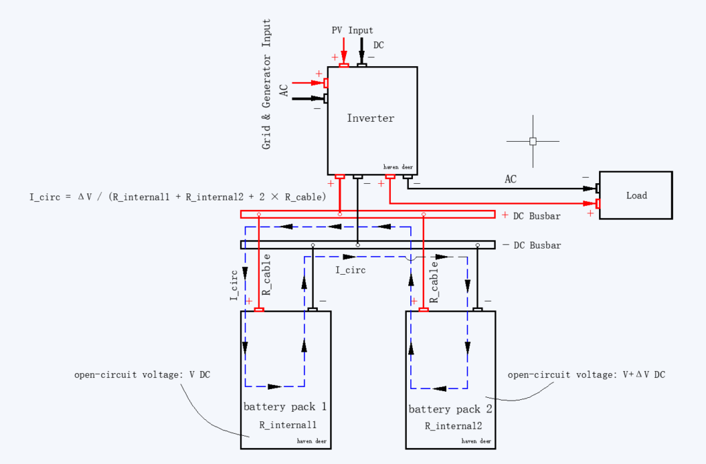
The primary physical risk when connecting DC sources in parallel is circulating current (I_circ). When packs with unequal open-circuit voltages share a DC busbar, current flows directly from the higher-voltage pack into the lower-voltage pack, bypassing the load.
Ohm’s Law dictates circulating current magnitude across the total loop resistance:
I_circ = ΔV / (R_internal1 + R_internal2 + 2 × R_cable)
Where:
I_circ = Circulating current between battery packs (A)
ΔV = Open-circuit terminal voltage difference between packs (V)
R_internal1, R_internal2 = Internal DC resistance of Pack 1 and Pack 2 (Ω)
R_cable = Electrical resistance of the interconnecting DC cables (Ω)
1.3 Worked Calculation Example
Take two 51.2V 100Ah packs in parallel. Pack 1 rests fully charged at 54.0V DC open-circuit. Pack 2 sits discharged at 50.0V DC, creating a 4.0V DC differential (ΔV). Assuming each pack has an internal cell resistance of 8 mΩ (0.008 Ω) and the interconnecting DC cabling provides 4 mΩ (0.004 Ω) total loop resistance:
Total Loop Resistance = 0.008 Ω + 0.008 Ω + 0.004 Ω = 0.020 Ω I_circ = 4.0V / 0.020 Ω = 200A
Closing the DC circuit under these conditions produces a theoretical 200A surge. That spike trips overcurrent protection and creates severe localized thermal stress.
Engineering Tip: Verify that open-circuit terminal voltage differences across all 51.2V packs remain under 1.0V DC before paralleling. If ΔV exceeds 1.0V DC, cycle packs independently before closing the main DC disconnect.
Structured Master-Slave BMS control hierarchies eliminate these circulating current risks.
2. Core Operational Logic of Master-Slave BMS Topology
2.1 Functional Division: Master BMS vs. Slave BMS
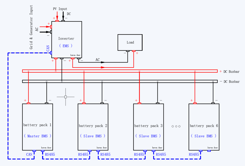
A master-slave BMS architecture decouples system energy management from pack-level protection. Rather than letting each pack talk directly to the hybrid inverter, one module acts as the sole communication gateway.
| Functional Parameter | Master BMS (DIP ID 1) | Slave BMS (DIP IDs 2–6) |
| Cell-Level Monitoring | Monitors local 16S cell string inside the Master pack | Monitors local 16S cell string inside each Slave pack |
| System Data Aggregation | Collects voltage, current, temperature, and SoC data from all online Slaves | Reports local operating data to Master BMS only |
| Inverter Communication | Maintains active CAN or RS485 closed-loop link to inverter EMS | Isolated from inverter EMS (internal communication only) |
| Charge/Discharge Control | Calculates and transmits system-level ACL and ADL limits | Executes local MOSFET or contactor protection |
| DIP Switch Address | Binary 0001 (ID 1) | Binary 0010 to 0110 (IDs 2–6) |
2.2 Address Assignment via DIP Switches
A 4-bit DIP switch on each module sets its network role. Binary coding assigns unique communication addresses across the parallel bank.
Master Designation (ID 1): Binary 0001 (Pin 1 ON, Pins 2–4 OFF) sets the Master BMS. This activates external CAN/RS485 links to the hybrid inverter.
Slave Designation (IDs 2–6): Binary 0010 through 0110 assigns unique internal polling addresses (IDs 2–6) to secondary packs.
Haven Deer wall-mounted home solar batteries (AL-WM512100 and AL-WM512200) rely on this addressing scheme for internal bus polling.
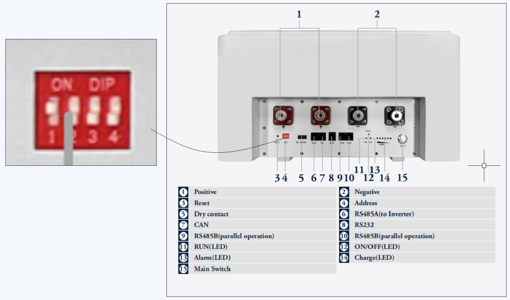
Common Mistake: Leaving DIP switches at factory default 0000 (ID 0 / Standalone mode). In multi-pack arrays, duplicate addresses cause bus collisions. The inverter drops closed-loop communication and faults back to open-loop voltage tracking.
For a broader evaluation of protocol selection, read our technical breakdown on Open-Loop vs. Closed-Loop BMS-Inverter Communication.
3. Communication Protocols & Closed-Loop Inverter Integration
3.1 Physical Layer: CAN Bus & RS485 Daisy-Chaining
The physical network runs on a dual-layer topology:
Internal Slave Bus (RS485): Shielded RS485 cables daisy-chain secondary modules via Link In and Link Out ports. The Master BMS continuously polls telemetry from each online Slave.
External Inverter Trunk (CAN Bus): A dedicated CAN port links the Master BMS directly to the hybrid inverter EMS (e.g., Haven Deer hybrid solar inverter ALL 4812000 Pro 12kW) in compliance with ISO 11898-2 physical layer specifications.
External Inverter Trunk (CAN Bus): A dedicated CAN port links the Master BMS directly to the hybrid inverter EMS (e.g., Haven Deer hybrid solar inverter ALL 4812000 Pro 12kW).
[Hybrid Inverter EMS]
          │ (CAN Bus Trunk: 250/500 kbps)
          ▼
   [Master BMS (ID 1)]
          │
          ├───────────────► (RS485 Daisy-Chain Link)
          ▼
   [Slave BMS (ID 2)] ────► [Slave BMS (ID 3)] ────► [Slave BMS (ID 4)]
3.2 Data Aggregation and EMS Protocol Dispatch
The Master BMS compiles pack parameters into a unified telemetry frame. It transmits aggregate SoC, SoH, total DC bus current, and dynamic operational limits to the inverter EMS.
The Master BMS dynamically calculates Allowable Charge Limits (ACL):
ACL_system = min(Σ ACL_slave_i, I_inverter_charge_max)
Where:
ACL_system = Total allowable charge current commanded to the inverter (A)
Σ ACL_slave_i = Sum of real-time maximum allowable charge currents reported by online Slaves (A)
I_inverter_charge_max = Maximum rated charging current capability of the Hybrid Inverter (A)
Worked Calculation Example
Three parallel Haven Deer AL-WM512200 batteries provide a theoretical 600A charge capacity (200A × 3).
However, the Haven Deer ALL 4812000 Pro 12kW inverter caps total charging at 160A. The Master BMS clamps ACL_system to 160A to protect inverter power electronics.
When a pack reaches 95% SoC, its local BMS throttles individual ACL_slave to 20A. The Master recalculates system limits and updates the CAN frame immediately. The inverter throttles output accordingly.
For more detail on system-level control logic, read our guide to how an integrated solar energy management system coordinates PV, battery, grid, and generator power flow.
4. Preventing Circulating Currents and Thermal Stress in Parallel Systems
4.1 Busbar Impedance Matching & Cable Equalization
BMS firmware cannot overcome flawed DC busbar geometry. Conductor impedance mismatches drive unequal current sharing across parallel modules under heavy load. Electrical cable resistance is defined by:
R_cable = ρ × (L / A)
Where:
ρ = Electrical resistivity of copper conductor (approximately 1.68 × 10⁻⁸ Ω·m at 20°C)
L = Total conductor path length (m)
A = Cross-sectional area of conductor (m²)
Wire the parallel bank diagonally rather than pulling positive and negative feeds from the first pack. Diagonal cross-wiring equalizes conductor path resistance.
Engineering Tip: Match cable gauge and length across all battery-to-busbar interconnects down to the millimeter. Unmatched lengths unbalance high-current charge and discharge sharing.
4.2 Automated Pre-Charge and Dynamic SoC Threshold Control
Haven Deer floor-standing off-grid solar batteries (MB512300 and MB512346) integrate dedicated pre-charge circuits for safe DC bus energization.
At startup, current flows through a pre-charge resistor to buffer the hybrid inverter’s large capacitive input stage. Once the module-to-bus voltage differential collapses, the main DC contactor closes. This eliminates destructive inrush spikes.
For additional information about battery protection mechanisms, read our guide on BMS Protection Layers: Voltage, Current & Thermal Safeguards.
5. Fault Isolation & Single-Pack Fail-Safe Protection
5.1 Slave Fault Handling Without System Interruption
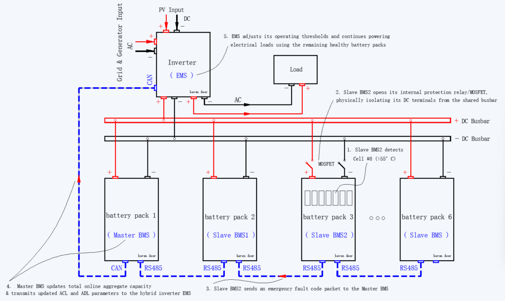
Master-slave architectures isolate single-pack faults without dropping the entire DC bus, fulfilling IEC 62619 industrial battery safety standards for operational continuity and thermal fault containment. When a module detects localized cell over-temperature or overvoltage, its Slave BMS immediately opens its local disconnect. The remaining bank stays online.
5.2 Single-Pack Fault Reaction Sequence
1. Local Fault Detection: The Slave BMS in Pack #3 flags a cell anomaly (e.g., over-temperature on Cell #8).
2. Hardware Disconnect: Slave #3 opens its internal DC contactor or solid-state MOSFETs, isolating itself from the shared busbar.
3. Telemetry Alarm Dispatch: Slave #3 broadcasts the fault code to the Master BMS over the internal RS485 bus.
4. Capacity Recalculation: The Master derates total available capacity (e.g., shedding one module to drop a six-pack 30.72kWh array to 25.60kWh).
5. CAN Communication Update: The Master pushes throttled charge and discharge current limits (ACL/ADL) to the inverter EMS via CAN.
6. Continued Operation: The inverter clamps its power draw to the revised envelope. Critical loads experience zero downtime.
5.3 Master BMS Redundancy & Communication Timeout Logic
If an internal RS485 link drops, the Master BMS initiates a heartbeat timeout. If the Slave fails to respond within the polling window, the Master sheds that unit from the active capacity calculation and logs a communication fault.
If external CAN communication to the inverter drops, the inverter EMS falls back to conservative open-loop voltage thresholds. This preserves cell safety until closed-loop telemetry recovers.
For additional troubleshooting information, refer to our guide to solar inverter error codes and alarm lists in the app.
6. Field Commissioning & Sizing Standards for Installers
6.1 Recommended Parallel Limits (Up to 6 Units)
While microcontrollers support more addresses, field engineering caps low-voltage parallel banks at 6 units. A 6-module ceiling prevents RS485 polling lag, stabilizes current sharing, and simplifies DC overcurrent protection.
| Battery Module Model | Form Factor | Unit Energy | Recommended Parallel Units | Aggregate System Energy | Maximum Continuous DC Discharge |
| AL-WM512100 | Wall-Mounted | 5.12 kWh | Up to 6 Units | 30.72 kWh | 600 A |
| AL-WM512200 | Wall-Mounted | 10.24 kWh | Up to 6 Units | 61.44 kWh | 1200 A |
| MB512300 | Mobile Cabinet | 15.0 kWh | Up to 6 Units | 90.0 kWh | 1200 A |
| MB512346 | Mobile Cabinet | 18.0 kWh | Up to 6 Units | 108.0 kWh | 1200 A |
6.2 Installer Commissioning Protocol
Commission multi-pack parallel LiFePO4 banks using this sequential verification procedure:
Mechanical & Load Verification
Confirm structural load ratings before mounting. Wall-mounted units (AL-WM series, 45.5–102 kg) demand reinforced structural walls. Mobile cabinets (MB series, 129–163 kg) require level, weight-rated industrial flooring.
Terminal Voltage Matching
Measure open-circuit terminal voltage across all modules with a calibrated DMM before landing DC cables. Verify voltage delta (ΔV) stays within 1.0V DC across all packs.
Hardware DIP Addressing
Assign DIP switch addresses before energizing the bus. Set Pack #1 to 0001 (Master ID 1). Set subsequent packs to 0010 through 0110 (IDs 2–6). Never leave parallel packs at the 0000 standalone default.
Communication Interconnects
Daisy-chain shielded RS485 cables between Link In and Link Out ports across all Slaves. Connect the Master BMS CAN port to the hybrid inverter using a dedicated twisted-pair CAN cable.
Sequential Energization
Close the Master DC breaker first to initialize communication bus telemetry. Once online, energize Slave breakers sequentially. Verify that the inverter registers closed-loop communication and displays true aggregate capacity.
For a comprehensive installation guide, refer to our solar commissioning checklist for installers, covering first-time setup.
7. Frequently Asked Questions
Why is a Master-Slave architecture required for parallel lithium battery banks?
Without a master-slave topology, parallel packs operate blindly without centralized coordination. The Master BMS aggregates SoC, voltage, and dynamic current limits into a single telemetry frame for the hybrid inverter EMS.
What happens if DIP switch addresses are incorrectly configured?
Duplicate IDs or an unassigned Master (ID 1) trigger communication bus collisions. The hybrid inverter drops closed-loop communication, logs a BMS communication fault, and falls back to open-loop voltage tracking.
How many Haven Deer battery modules can be connected in parallel?
Haven Deer caps parallel arrays at 6 units per bank. This yields up to 61.44kWh in wall-mounted configurations (AL-WM series) or 108.0kWh in mobile cabinets (MB series).
Can I connect different battery capacities (e.g., 5.12kWh and 10.24kWh) in parallel?
No. Parallel banks require identical capacity, cell chemistry, and BMS firmware. Mismatched capacities unbalance current sharing and accelerate cell degradation.
How does the Master BMS calculate total State of Charge (SOC)?
The Master BMS calculates aggregate SoC using a capacity-weighted sum across all online modules:
SoC_system = (Σ Ah_remaining / Σ Ah_total) × 100%
What is circulating current in parallel battery banks?
Circulating current flows between parallel packs with unequal terminal voltages. Instead of supplying external loads, current loops parasitically between modules, generating localized heat and severe cell stress.
What voltage differential is acceptable before connecting batteries in parallel?
Hold the open-circuit terminal voltage delta within 1.0V DC before landing DC cables. Excessive deltas drive high inrush currents.
Does a failure in one Slave battery pack shut down the entire system?
No. The faulted Slave BMS trips its internal contactor or solid-state MOSFETs to isolate the pack. The Master derates system capacity and updates dynamic limits immediately. The remaining bank stays online.
What physical communication interface connects the Master BMS to Haven Deer inverters?
A dedicated CAN bus or RS485 trunk links the Master BMS directly to the inverter’s BMS port (fully compatible with Haven Deer ALL 486000 Pro and ALL 4812000 Pro units).
Can Haven Deer parallel battery systems be expanded at a later date?
Yes. Additional modules must share identical model specifications and firmware. Balance the new module’s terminal voltage to within 1.0V DC of the operational bank before landing DC interconnects.
8. Need Engineering Support for Multi-Pack Battery System Design?
Multi-pack ESS engineering demands matched DC conductor impedance, coordinated overcurrent protection, and verified BMS communication protocols. Whether deploying residential backup arrays or commercial microgrids, Haven Deer’s application engineers review busbar architectures, verify DIP addressing, and validate closed-loop inverter compatibility.
Contact our technical team for custom single-line diagrams (SLDs), communication topology sign-offs, and factory-matched off-grid solar power system specifications.