Quick Answer: Grade A LiFePO4 cells feature tight capacity matching, low internal resistance, and rigid aluminum enclosures built for demanding BESS applications. Off-grid BESS designs stack these cells into a 16S configuration (51.2V nominal). Expect cycle life to reach ≥6,000 cycles at 90% DoD and ≥10,000 cycles at 80% DoD. Paired with a layered BMS and hybrid inverters, Grade A packs secure dependable long-term power.
1. Electrochemistry & Form Factor: Why Prismatic LiFePO4 Leads Off-Grid ESS
A reliable off-grid solar power system architecture depends on a battery chemistry that tolerates daily cycling, high discharge currents, and thermal stress without compromising safety. LiFePO4 meets these demands, and prismatic cells are widely used in residential and commercial storage thanks to their high capacity and compact, stackable design.
1.1 Thermal Stability & Safety of LiFePO4 Cathode Chemistry
LiFePO4 derives its thermal stability directly from its robust olivine crystal matrix. Unlike nickel chemistries (NMC/NCA), strong P-O covalent bonds prevent oxygen release during thermal decomposition.
Under really bad fault conditions—like overcharging, a short circuit, or physical damage—this design keeps a failing cell from turning into a thermal runaway fire propagation risk under UL 9540A evaluation protocols. Nickel-based materials release oxygen when they get hot, which is what pushes the runaway to spread to nearby cells.
Intrinsic thermal stability makes LiFePO4 the safest baseline for high-capacity residential and commercial BESS.
1.2 Mechanical Integrity: Prismatic Aluminum Shell vs. Pouch & Cylindrical Cells
Commercial lithium cells come in three physical form factors: cylindrical, pouch (soft-pack), and prismatic (rigid aluminum casing).
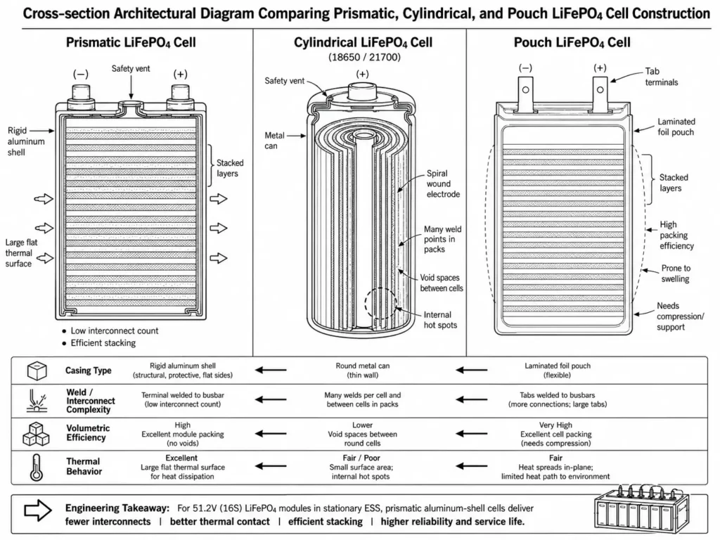
In stationary energy storage, prismatic aluminum-shell cells provide distinct structural, thermal, and economic advantages:
- Volumetric Efficiency: Prismatic cells stack without dead air space, maximizing enclosure volume utilization compared to cylindrical packs.
- Reduced Interconnect Complexity: A standard 51.2V module requires only 16 series-connected cells. Fewer cells mean fewer busbars, drastically cutting failure points compared to thousands of cylindrical welds.
- Thermal Dissipation: Large, flat aluminum walls provide direct surface contact for thermal interface materials and heat sinks, eliminating internal hot spots.
- Pressure Management: Integrated safety vents relieve excess internal pressure in a controlled manner, preventing catastrophic enclosure rupture during extreme fault conditions.
| Form Factor | Mechanical Casing | Weld Point Density (for 10kWh) | Volumetric Efficiency | Thermal Dissipation |
| Prismatic | Rigid Aluminum Shell | Very Low (16–32 joints) | High (Optimal stacking) | Superior (Flat surface contact) |
| Cylindrical | Metal Can (18650/21700) | Extremely High (>1,000 joints) | Moderate (Void spaces) | Complex (Internal hot spots) |
| Pouch | Laminated Aluminum Foil | Low to Moderate | High | Poor (Prone to swelling) |
Engineering Tip: During site commissioning, verify module spacing against manufacturer specs to ensure uninhibited airflow and safe heat rejection.
2. Cell Grade Classification: Grade A vs. Grade B in Critical Storage Applications
Factory sorting separates Grade A cells from lower tiers using capacity binning and internal resistance (IR) testing. Identifying cell grades prevents premature pack failure in off-grid BESS.
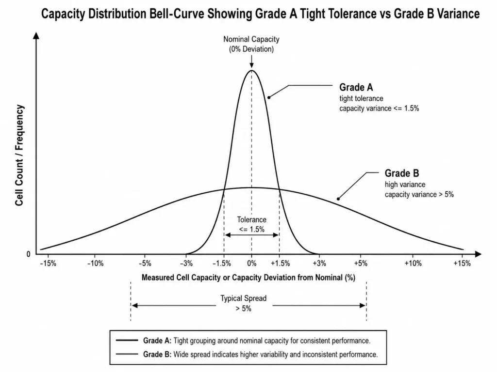
2.1 Factory Sorting Metrics: Capacity Matching, IR Sorting, and Delta-V
Grade A cells comply with IEC 62619 safety standards for industrial lithium batteries, meeting strict OEM tolerances across four core quality metrics to establish the foundation for 51.2V modules:
- Capacity Consistency: Binned within tight capacity tolerances (typically ≤ ±0.5%), preventing early cell cutoff during discharge.
- Internal Resistance (AC IR): Matched within ±0.05 mΩ to ensure uniform heat generation and passive current sharing across cells.
- Self-Discharge Rate (Delta-V): Stored cell voltage drop (ΔV) remains uniform over aging periods, minimizing passive SoC drift.
- Physical Geometry: Inspected for flat aluminum casing, zero terminal oxidation, and precise laser weld integrity before pack assembly.
| Parameter | Grade A Prismatic Cells | Grade B / Secondary Cells |
| Capacity Consistency | Strict tolerance (≤ ±0.5% variance) | High variance (≥ 2–5% spread) |
| Internal Resistance (AC IR) | Uniform IR matching (±0.05 mΩ) | Widely scattered IR values |
| Self-Discharge Rate | Low, predictable ΔV loss | Elevated/erratic self-discharge |
| BMS Cell Balance Stability | Minimal passive balancing needed | Heavy passive/active balancing required |
| Traceability | Full factory QR code and batch data | Erased, fake, or missing QR codes |
2.2 Field Degradation Risks of Lower-Grade / Repurposed Cells
B-grade or repurposed EV surplus cells offer upfront cost savings but introduce severe long-term degradation risks:
- Premature Pack Imbalance: In a 16S pack, the weakest cell dictates overall capacity. High-IR cells trigger early BMS over-voltage or under-voltage cutoffs, limiting usable kWh output.
- Increased BMS Balancing Demand: Wide cell-to-cell voltage deltas force continuous BMS passive balancing, overheating balancing resistors and accelerating BMS board failure.
- Thermal Reliability Risk: Inconsistent internal resistance creates localized hot spots within the pack, accelerating chemical degradation and thermal runaway risk.
Common Mistake: Buying cheap cells without verified factory test reports. While initial capacity tests may pass on day one, cell-to-cell divergence accelerates within 100 to 200 cycles, cutting usable storage.
4-Point Factory Inspection Checklist for Grade A Cell Verification
[ ] Perform a 0.5C full capacity charge/discharge cycle to verify actual Ah rating matches the factory label.
[ ] Scan laser-etched terminal QR codes to verify factory production dates, batch numbers, and original grading reports.
[ ] Measure open-circuit voltage (OCV); confirm ΔV between all 16 cells is within OEM specs (typically ≤ 5 mV) prior to assembly.
[ ] Test AC internal resistance with a 1 kHz micro-ohm meter; confirm all cells meet specified target tolerances.
3. 16S Architecture & Multi-Layer BMS Control Principles
System voltage architecture dictates conversion efficiency, cable sizing, and inverter operating windows. Modern lithium BESS modules favor 16S prismatic topologies over legacy 12V lead-acid blocks.
3.1 Voltage Matching: Why 51.2V (16S) Outperforms 48V (15S) Topologies
A standard LiFePO4 cell operates at a nominal voltage of 3.2V. Connecting 16 cells in series (16S) establishes a nominal pack voltage of 51.2V.
Budget suppliers often shortcut design with 15S packs (48.0V nominal). This causes premature inverter cutoffs during deep discharge cycles under heavy loads.
Nominal Pack Voltage = Number of Cells in Series × Nominal Cell Voltage
Vnom = 16 × 3.2V = 51.2V
Operating Voltage Window = 16 × 2.5V (Typical Low Voltage Limit) to 16 × 3.65V (Typical High Voltage Limit)
Vrange = 40.0V DC to 58.4V DC
Operating a 16S 51.2V architecture delivers distinct engineering advantages:
- Inverter Voltage Compatibility: A 16S topology operates from 40.0V to 58.4V DC. This window aligns with standard 48V low-voltage hybrid inverters (e.g., Haven Deer ALL 486000 Pro and ALL 4812000 Pro), preventing nuisance low-voltage disconnects.
- Reduced I²R Thermal Losses: Higher voltage reduces current draw for the same power output (P = V × I). Lowering current minimizes resistive heat generation (I²R) in DC cabling and power electronics, improving round-trip efficiency (RTE).
15S System (at 45V operating voltage): 6,000W / 45V ≈ 133.3A
16S System (at 48V operating voltage): 6,000W / 48V = 125.0A
| Topology | Nominal Voltage | Full Charge Voltage | Discharge Cutoff Voltage | Inverter Current @ 6kW Load | Cable Thermal Losses (I²R) |
| 15S Configuration | 48.0V DC | 54.75V DC | 37.5V DC | ~133.3A | Higher Heat Generation |
| 16S Configuration | 51.2V DC | 58.40V DC | 40.0V DC | ~125.0A | Lower Loss / Higher Efficiency |
3.2 BMS Cell Balancing and Closed-Loop Communication (CAN / RS485)
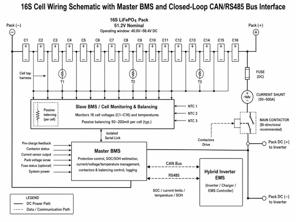
The Battery Management System (BMS) acts as the primary safety controller for the battery pack. A multi-layer BMS manages two main functions: cell-level monitoring and battery communication with the hybrid inverter system.
[Prismatic Cells (16S)] ◄───► [Cell Tap Harness] ───► [Slave BMS (Balancing)]
                                                                 │
                                                                 ▼
[Hybrid Inverter EMS] ◄────── [CAN / RS485 Bus] ◄────── [Master BMS (Logic)]
Cell Voltage Monitoring: Sense leads track cell-level ΔV in real time. If any cell breaches safety thresholds, the BMS opens main contactors or protective MOSFETs immediately.
Passive Cell Balancing: During top-of-charge phases, the BMS engages passive balancing circuits to burn off excess charge through shunt resistors. This maintains cell voltage alignment across all 16 series elements.
Closed-Loop Inverter Telemetry: Rather than relying on inaccurate terminal voltage curve estimation, the BMS broadcasts active SoC, maximum charge/discharge current limits (CCL/DCL), and cell temperatures via CAN/RS485. This live telemetry guides the solar energy management system as it coordinates PV, battery, grid, and generator power flow, preventing cell overload during multi-source switching.
4. Cycle Life Engineering: Calculating Lifetime Output Across DoD Thresholds
Evaluating Grade A LiFePO4 prismatic cells requires quantifying degradation behavior under continuous daily cycling.
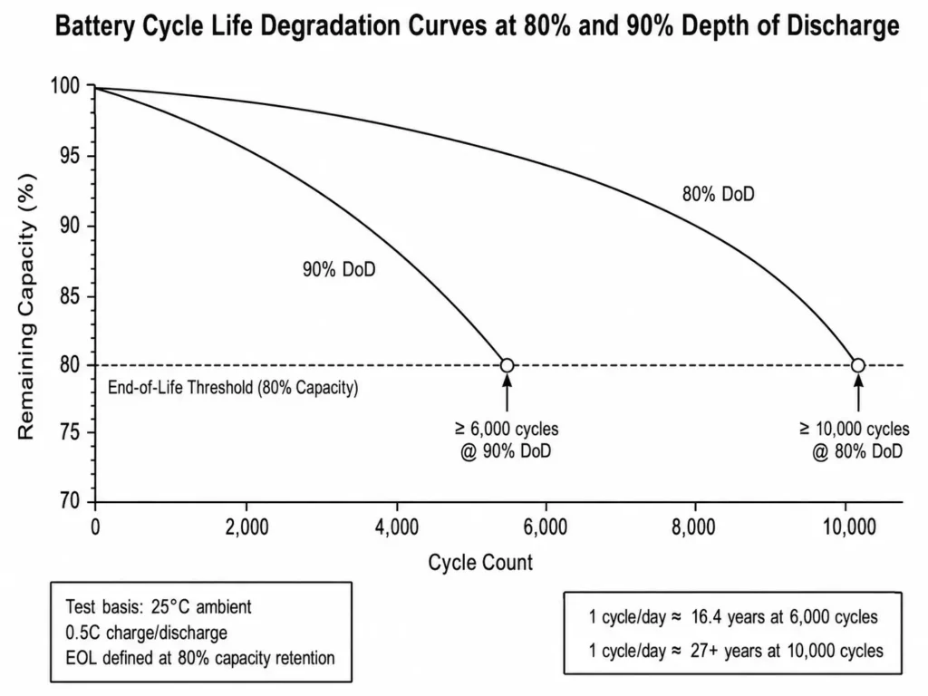
4.1 Quantifying Lifespan: 6,000 Cycles @ 90% DoD vs. 10,000 Cycles @ 80% DoD
Operating depth directly dictates mechanical electrode stress and solid-electrolyte interphase (SEI) layer degradation rate.
Under standard laboratory conditions (25°C ambient, 0.5C charge/discharge rate, 80% End-of-Life retention):
- 90% Depth of Discharge: A Grade A prismatic module delivers ≥ 6,000 cycles.
- 80% Depth of Discharge: Lowering discharge depth to 80% reduces mechanical cell stress, raising cycle life to ≥ 10,000 cycles.
In daily off-grid operation (1 cycle per day, 365 cycles per year):
- 6,000 cycles @ 90% DoD equals roughly 16 years of continuous cycling.
- 10,000 cycles @ 80% DoD equals roughly 27 years of continuous cycling.
Limiting daily discharge to 80% DoD optimizes return on investment by extending usable service life past 25 years.
4.2 Levelized Cost of Storage (LCOS) Formula & Calculation Example
Calculating Levelized Cost of Storage (LCOS) based on NREL energy storage financial models quantifies overall economic performance by tracking total cost per delivered kWh over system operating life.
Total Lifetime Energy Throughput = Nominal Battery Energy × Depth of Discharge × Cycle Life × Round-Trip Efficiency
E_lifetime = E_pack × DoD × N_cycles × η
Worked Calculation Example:
Consider a Haven Deer AL-WM512200 wall-mounted home solar battery:
- Nominal Energy (E_pack): 10.24 kWh (51.2V × 200Ah)
- Selected Operating Depth (DoD): 80% (0.80)
- Rated Cycle Life (N_cycles): 10,000 cycles
- Round-Trip Efficiency (η): 95% (0.95)
E_lifetime = 10.24 kWh × 0.80 × 10,000 × 0.95 = 77,824 kWh
At 80% DoD, a single 10.24 kWh module yields 77,824 kWh of cumulative energy throughput before reaching 80% EOL. Dividing initial hardware cost by lifetime energy throughput yields true LCOS for storage comparisons.
| Battery Module Model | Nominal Energy | DoD Percentage | Cycle Life Rating | Lifetime Energy Throughput |
| AL-WM512100 | 5.12 kWh | 90% DoD | ≥ 6,000 Cycles | ~26,265 kWh |
| AL-WM512100 | 5.12 kWh | 80% DoD | ≥ 10,000 Cycles | ~38,912 kWh |
| AL-WM512200 | 10.24 kWh | 90% DoD | ≥ 6,000 Cycles | ~52,531 kWh |
| AL-WM512200 | 10.24 kWh | 80% DoD | ≥ 10,000 Cycles | ~77,824 kWh |
| MB512300 | 15.00 kWh | 80% DoD | ≥ 10,000 Cycles | ~114,000 kWh |
| MB512346 | 18.00 kWh | 80% DoD | ≥ 10,000 Cycles | ~136,800 kWh |
5. Temperature Dependencies: Low-Temperature Cutoffs & Thermal Protection
Operating temperature governs lithium-ion mobility, charge transfer kinetics, and round-trip efficiency in off-grid BESS setups.
                       [Operating Temperature Scale]

 ◄─── Discharging Allowed ───┤ 0°C ├─── Charging & Discharging Allowed ───►
   (Sub-Zero: -15°C to 0°C)  │     │     (Normal: 0°C to 50°C)
                             │
                             ▼
               [0°C Charge Cutoff Triggered]
                (Prevents Lithium Plating)
5.1 0°C Charge Cutoff Mechanisms to Prevent Lithium Plating
Charging below 0°C represents the most critical thermal failure vector for LiFePO4 cells.
Below 0°C, slowed lithium-ion diffusion causes metallic lithium to deposit on the graphite anode instead of intercalating—a failure mode detailed in low-temperature lithium plating dynamics.
Lithium plating causes two catastrophic failure modes:
- Permanent Capacity Loss: Plated lithium immobilizes active ions, permanently degrading pack Ah capacity.
- Dendrite Formation: Metallic tendrils pierce the separator, causing internal micro-shorts and thermal runaway.
To prevent cell destruction, internal NTC thermistors trigger a BMS charge cutoff at 0°C, blocking PV and generator input current immediately.
5.2 Sub-Zero Discharging Performance down to -15°C / -20°C
While sub-zero charging causes immediate degradation, low-temperature discharging remains viable under controlled C-rates.
LiFePO4 prismatic modules deliver discharge current down to -15°C or -20°C, depending on casing insulation and rating. Increased electrolyte viscosity at sub-zero temperatures raises internal resistance (IR), inducing transient voltage sag under heavy loads.
| Operating Mode | Temperature Limits | BMS Automated Control Response |
| Safe Charging | 0°C to 50°C | Normal charge current permitted per C-rate profile |
| Low-Temp Charge Cutoff | < 0°C | Ingress charge current blocked; low-temp alarm sent via CAN/RS485 |
| Safe Discharging | -15°C to 50°C (WM) / -20°C to 55°C (MB) | Active discharge permitted; BMS scales max discharge C-rate based on temp |
| High-Temp Cutoff | >50°C (Charge) / >55°C (Discharge) | Contactors trip; charging/discharging disabled until temperature drops |
Engineering Tip: For effective inverter thermal management in IP21/IP22 housings, allow clearance around ventilation openings. Install battery modules in climate-controlled spaces and avoid mounting unheated packs on uninsulated exterior walls subject to sub-freezing drafts.
Common Mistake: Overriding BMS low-temperature charge limits in inverter settings to force charge cold packs. Charging below 0°C destroys cell capacity within minutes via severe plating.
Cold-Weather Off-Grid Battery Installation Checklist
- [ ] Verify local ambient temperatures stay within manufacturer charge specs (0°C to 50°C) during peak PV generating hours.
- [ ] Test BMS low-temperature cutoff during commissioning via closed-loop CAN bus diagnostic telemetry.
- [ ] Mount battery packs on interior load-bearing structures away from cold-air infiltration points.
- [ ] Program generator auto-start protocols to maintain ambient thermal management equipment during prolonged grid outages.
6. Integration Guide: Deploying LFP Storage in Haven Deer Off-Grid Kits
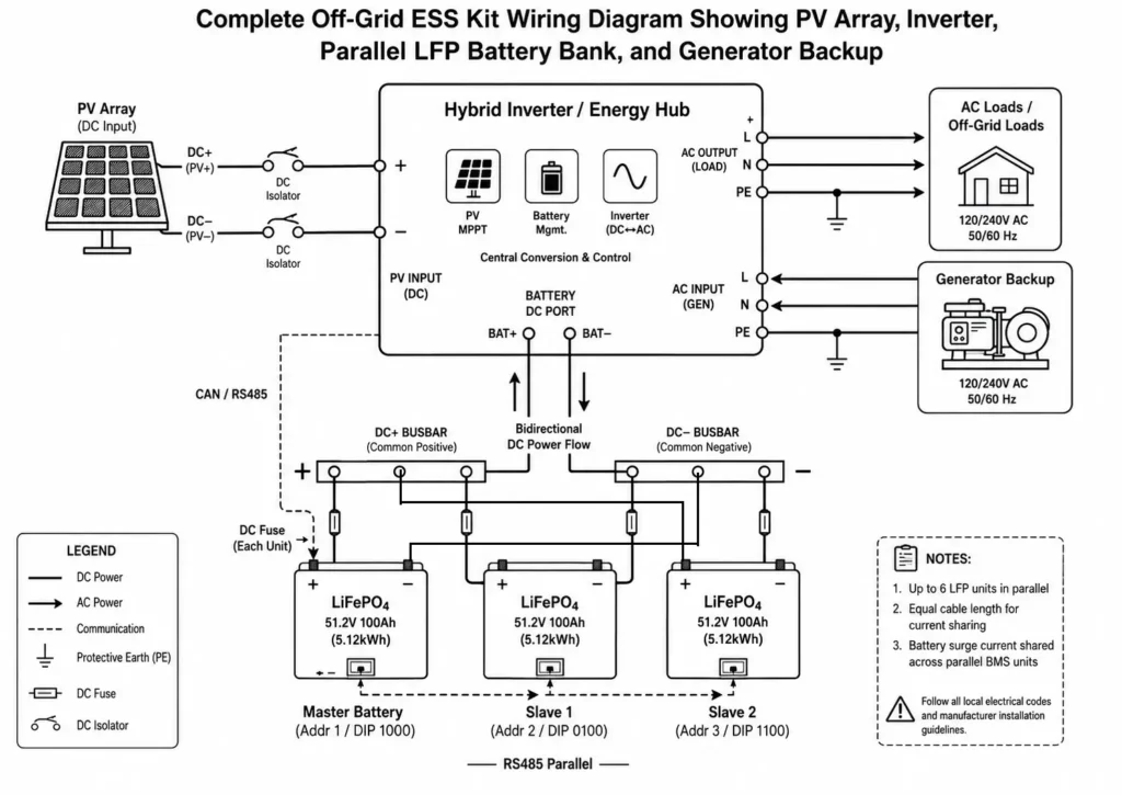
Designing off-grid BESS requires evaluating single MPPT vs. dual MPPT in off-grid solar kits to match PV array sizing, inverter surge ratings, and Grade A pack capacity into a reliable system.
6.1 Sizing Battery Storage for Autonomy & Inverter Surge Capacities
Off grid solar system sizing begins with matching the off-grid hybrid inverter’s continuous output power and peak surge rating to inductive loads such as water pumps, refrigeration compressors, and power tools:
- ALL 486000 Pro hybrid solar inverter: Delivers 6,000W continuous output with a peak surge rating of 12,000VA (5 seconds).
- ALL 4812000 Pro hybrid solar inverter: Delivers 12,000W continuous output with a peak surge rating of 22,000VA.
Battery banks must supply peak DC current without tripping BMS overcurrent protection (OCP):
Required DC Current ≈ Peak Inverter Surge Power / (Inverter Efficiency × Minimum Battery Voltage)
I_peak ≈ 12,000VA / (0.93 × 42.0V DC) ≈ 307A DC
To support a 307A peak surge:
- A single AL-WM512100 (100A continuous / 130A peak) trips its BMS under a 307A surge, requiring at least 3 units in parallel.
- A single AL-WM512200 (200A continuous / 260A peak) or MB512300 (200A continuous) handles higher continuous loads but needs a second parallel module for full 307A surge coverage.
Paralleling modules splits surge current across multiple BMS contactors, preventing individual unit trips.
6.2 Parallel Expansion Limits (Up to 6 Units) & Master-Slave DIP Addressing
To scale an off-grid solar power system across 5kWh to 60kWh residential and commercial requirements, Haven Deer wall-mounted and mobile cabinet modules connect in parallel DC configurations.
[Inverter CAN Bus]
        │
        ▼
[Master Battery] ───(RS485 Parallel)───► [Slave Battery 1] ───► [Slave Battery 2]
To configure parallel battery arrays:
- Parallel Expansion Limit: Limit parallel arrays to 6 units max to maintain stable RS485 bus telemetry and current balance. Maximum array capacity reaches 61.44 kWh (AL-WM512200) or 108 kWh (MB512346).
- Master-Slave Address Assignment: Set DIP switch communication addresses on each BMS board prior to powering up the system:
- Unit 1 (Master): Set DIP address to ID 1; connect main CAN/RS485 port directly to the hybrid inverter.
- Unit 2 (Slave 1): Set DIP address to ID 2; daisy-chain RS485 input to Master.
- Unit 3 (Slave 2): Set DIP address to ID 3; continue sequential RS485 bus loop.
- Equal Cable Resistance: Use identical cable lengths and AWG gauges for all module runs to the common busbar to prevent unequal current sharing.
Form Factor Considerations:
- Wall-Mounted Series (AL-WM512100 / AL-WM512200): Housed in IP21 enclosures for indoor wall mounting. Given unit weights (AL-WM512100: 45.5 kg; AL-WM512200: 102 kg), mount only to structural studs or masonry load-bearing walls.
- Floor-Standing Mobile Cabinet off-grid solar battery Series (MB512300 / MB512346): Housed in IP22 cabinets fitted with heavy-duty casters. Designed for equipment room floors without wall mounting requirements (MB512300: 129 kg; MB512346: 163 kg). Note: MB units are free-standing cabinets, not standard 19-inch rack modules.
| Battery Model | Form Factor | Capacity / Energy | Max Cont. Discharge | IP Rating | Recommended Max Parallel |
| AL-WM512100 | Wall-Mounted | 100Ah / 5.12 kWh | 100A | IP21 | Up to 6 Units (30.72 kWh) |
| AL-WM512200 | Wall-Mounted | 200Ah / 10.24 kWh | 200A | IP21 | Up to 6 Units (61.44 kWh) |
| MB512300 | Floor Mobile Cabinet | 300Ah / 15.00 kWh | 200A | IP22 | Up to 6 Units (90.00 kWh) |
| MB512346 | Floor Mobile Cabinet | 346Ah / 18.00 kWh | 200A | IP22 | Up to 6 Units (108.00 kWh) |
7. Frequently Asked Questions (FAQ)
What are Grade A LiFePO4 prismatic cells?
Grade A cells meet strict OEM specs for capacity retention (≤ ±0.5% spread), AC internal resistance (±0.05 mΩ), and casing geometry. They ensure uniform current distribution and long service life in BESS packs.
Why are prismatic cells preferred over cylindrical cells for solar ESS?
Prismatic cells feature rigid aluminum shells, efficient internal space utilization, effective surface-contact heat dissipation, and simplified cell interconnection. A typical 51.2V LiFePO4 battery module uses 16 series-connected cells, reducing internal connection complexity compared with battery packs built from large numbers of cylindrical cells.
What is the advantage of a 16S 51.2V architecture over 15S 48V?
A 16S configuration establishes a nominal voltage of 51.2V and an operating voltage range of approximately 40.0V DC to 58.4V DC, matching the operating requirements of many modern 48V-class hybrid inverters. For the same power output, higher battery voltage reduces current demand and helps lower I²R losses in cables and power electronics.
How many cycles can I expect from Haven Deer Grade A LiFePO4 batteries?
Haven Deer Grade A LFP battery modules are rated for ≥ 6,000 cycles at 90% Depth of Discharge (DoD) and ≥ 10,000 cycles at 80% DoD under standard test conditions (25°C ambient temperature), supporting long-term daily cycling applications when properly installed and operated.
What happens if ambient temperatures drop below freezing (0°C)?
The BMS inhibits charging current at 0°C to prevent lithium plating and permanent anode damage. Discharging remains active down to -15°C (WM) or -20°C (MB).
Can I connect Haven Deer wall-mounted batteries in series to increase system voltage?
No. Never connect 51.2V modules in series. Series connection exceeds BMS voltage ratings. Expand storage capacity and current output exclusively through parallel busbars (up to 6 units).
What BMS communication protocols are supported?
Haven Deer BMS units support CAN bus and RS485 communication interfaces for closed-loop battery monitoring and dynamic charging parameter management with compatible hybrid inverters and monitoring systems.
What is the difference between the WM and MB battery series?
The AL-WM series (5.12kWh and 10.24kWh) features IP21 wall-mounted battery enclosures designed for indoor installation. The MB series (15.0kWh and 18.0kWh) features IP22 floor-standing mobile cabinet enclosures designed for larger residential, agricultural, and commercial energy storage applications.
Why is closed-loop BMS communication important?
Closed-loop communication broadcasts active SoC, CCL/DCL limits, and cell thermal data directly to the inverter EMS. This eliminates terminal voltage drift errors and optimizes dynamic charge profiles.
Does a LiFePO4 battery bank require active room cooling?
Under normal residential and commercial operating conditions, prismatic aluminum battery enclosures provide effective passive heat dissipation. However, installation areas should maintain adequate ventilation and remain within the recommended operating temperature range.
How does cell balancing work in Haven Deer battery packs?
The BMS uses passive balancing circuits during top-of-charge phases. Shunt resistors burn off excess energy as heat from high-voltage cells, aligning cell ΔV across all 16 series elements.
What is the factory warranty on Haven Deer LiFePO4 batteries?
Haven Deer residential and commercial LiFePO4 energy storage battery modules are covered by a standard 5-year factory warranty.
8. Need Custom Engineering Support for Your Off-Grid Battery Storage System?
Proper BESS sizing requires matching PV generation, inverter surge ratings, and LFP discharge curves to maintain power availability.
Whether you are deploying residential storage, agricultural microgrids, or commercial backup, Haven Deer’s field application engineers deliver system sizing, single-line diagrams (SLD), and OEM/ODM customization.
Contact Haven Deer for direct application engineering support.