Quick Answer: A 51.2V (16S) LiFePO₄ battery uses a Battery Management System (BMS) to monitor cell voltages, pack current, and temperatures, and to estimate State of Charge (SoC) and State of Health (SoH). Fast hardware protection cuts off the pack during overvoltage, undervoltage, overcurrent, short-circuit, and over-temperature events, while cell balancing and low-temperature charge limits help keep cycling stable and extend service life. This reduces the risk of field failures in residential and off-grid solar power system installations.
1. The Architectural Role of the BMS in LiFePO4 Safety & System Hierarchy
Modern solar energy storage systems rely on a coordinated two-layer control architecture: the Battery Management System (BMS) and the Energy Management System (EMS). Inside a complete off-grid solar power system architecture, drawing a hard boundary between battery protection and system dispatch prevents integration failures.
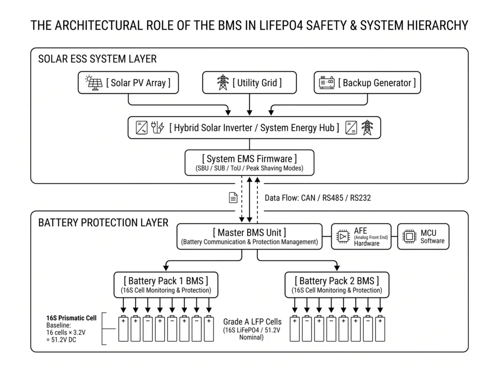
1.1 BMS vs. EMS: Distinguishing Cell-Level Safety from System Strategy
Commissioning engineers often confuse the BMS with the EMS. In reality, their operational boundaries are completely separate:
- Battery Management System (BMS): Operates strictly at the pack level. It continuously samples telemetry, balances cells, and trips hardware safety interlocks. The unit logs cell voltages, pack current, thermistor temperatures, SoC, and SoH. If any parameter breaches safety thresholds, the BMS opens solid-state MOSFETs or drops mechanical contactors to isolate the pack. It never dictates operational priority modes like Solar-Battery-Utility (SBU) or Solar-Utility-Battery (SUB).
- Energy Management System (EMS): A solar energy management system operates at the hybrid inverter and plant supervisory level. The EMS routes active power across solar PV arrays, the utility grid, standby diesel generators, battery banks, and facility loads. It schedules charge and discharge cycles based on utility tariffs, solar yield, and configured strategies like Time-of-Use (ToU) or Peak Shaving.
Safety overrides strategy every time. If the inverter demands excessive charging current, the BMS broadcasts dynamic charge limits over CAN or RS485. When cells overheat, the BMS throttles charge current or opens the main circuit to protect the pack.
| Parameter / Feature | Battery Management System (BMS) | Energy Management System (EMS) |
| Primary Scope | Cell safety, pack balancing, protection triggers | System energy flow, grid interaction, mode dispatch |
| Control Level | Individual cell voltage, temperature, and pack current | System PV, grid, generator, and load priority |
| Action Mechanism | MOSFET switching / contactor control for battery protection | Inverter PWM regulation and relay switching |
| Operating Modes | Autonomous hardware and firmware protection logic | Configurable strategy modes (SBU, SUB, ToU, Peak Shaving) |
| Communication | Internal CAN / RS485 communication with inverter | WiFi / 4G monitoring platform / mobile application |
1.2 The 16S Prismatic Cell Baseline (51.2V Nominal Topology)
To achieve reliable 48V-class energy storage, modern systems configure Lithium Iron Phosphate (LiFePO4) in a 16-series (16S) architecture. Grade A prismatic LiFePO4 cells run at a nominal 3.2V DC.
Connecting 16 prismatic cells in series establishes the standard nominal system voltage:
Nominal System Voltage = 16 cells × 3.2V/cell = 51.2V DC
Unlike legacy 15S builds, 16S natively matches the DC operating windows of modern 48V hybrid inverters. Standard Grade A prismatic cells (102Ah, 206Ah, 300Ah, and 346Ah) drop into wall-mounted racks and floor-standing enclosures to form scalable storage banks.
2. Voltage Protection Safeguards: Cell & Pack-Level Cutoff Engineering
Precise voltage control prevents premature cell degradation. Running Grade A LiFePO4 cells beyond electrochemical limits spikes internal resistance (ESR) and causes permanent capacity loss.
2.1 Overvoltage Protection (OVP) and Cell Balancing Thresholds
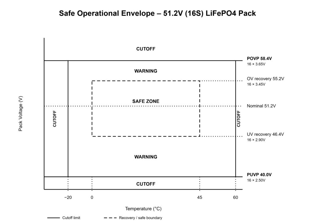
Overvoltage destroys cathode stability. Overcharging oxidizes the liquid electrolyte and stresses the electrode lattice. To prevent structural failure, the BMS enforces dual-stage hardware and firmware overvoltage limits across individual cells and the entire pack:
- Cell Overvoltage Protection (COVP) Trigger: 3.65V DC per cell
- Maximum Pack Overvoltage Protection (POVP) Trigger: 16 cells × 3.65V = 58.4V DC
- Cell Overvoltage Recovery Threshold: ≤ 3.45V DC per cell
If any single cell hits the COVP threshold, the BMS immediately trips the charge MOSFET or drops the main contactor while maintaining pack telemetry.
To maintain voltage uniformity across all 16 series-connected cells, the BMS integrates passive cell balancing logic:
- Balancing Initiation Voltage: Begins when individual cell voltage reaches the configured BMS balancing threshold during the constant-voltage (CV) charging phase.
- Balancing Delta Threshold (ΔV): Activates when the voltage spread between the highest and lowest cell exceeds configured millivolt limits.
- Balancing Action: Internal bleed resistors shunt bypass current off high-voltage cells to minimize delta-V during the absorb stage.
Engineering Tip: Set the hybrid inverter bulk charge voltage to roughly 56.0V DC (3.50V per cell). This gives the BMS sufficient headroom below the 58.4V POVP threshold, allowing passive bleed resistors enough time to resolve cell imbalances before cutoff.
2.2 Undervoltage Protection (UVP) and Deep Discharge Recovery
Deep discharge dissolves the copper anode current collector, causing internal micro-shorts on recharge.
To prevent irreversible structural damage, the BMS enforces defined lower cutoff boundaries:
- Cell Undervoltage Protection (CUVP) Trigger: 2.50V DC per cell
- Minimum Pack Undervoltage Protection (PUVP) Trigger: 16 cells × 2.50V = 40.0V DC
- Cell Undervoltage Recovery Threshold: ≥ 2.90V DC per cell (or per firmware recovery logic)
Shallow cycling extends cell life. While Haven Deer LiFePO4 batteries are rated for ≥10,000 cycles at 80% DoD and ≥6,000 cycles at 90% DoD, maintaining a conservative daily depth of discharge reduces mechanical electrode strain over multi-year deployments.
| Protection Parameter | Cell Level Trigger | Pack Level (16S) Trigger | Action / Delay | Recovery Condition |
| Overvoltage (COVP) | ≥ 3.65V DC | 58.4V DC | Open charge MOSFET or contactor via firmware logic | Cell voltage drops to ≤ 3.45V DC |
| Undervoltage (CUVP) | ≤ 2.50V DC | 40.0V DC | Open discharge MOSFET or contactor via firmware logic | Cell voltage rises to ≥ 2.90V DC or active charge current detected |
| Balancing Threshold | 3.40V DC (typical) | Pack-dependent | Shunt current through internal bleed resistors | Cell delta-V drops below configured deadband |
When a pack sits dormant in a deep-discharge state, the BMS drops into sleep mode to halt parasitic drain. Haven Deer wall-mounted home solar batteries (AL-WM512100 5.12kWh and AL-WM512200 10.24kWh) support automated 0V lithium wake-up protocols. When paired with hybrid solar inverters like the ALL 486000 Pro or ALL 4812000 Pro, incoming PV or grid power sends a wake-up pulse to clear low-power lockouts and safely restore normal charging.
3. Overcurrent and Short-Circuit Protection Mechanics
Inrush current must not trigger nuisance trips. Off-grid inductive loads like well pumps and compressors pull heavy locked-rotor startup surges, so inverter surge power must be matched with the battery’s discharge capability. The BMS protection stage must ride through transient surges while maintaining instant trip capability during genuine short circuits.
3.1 Dual-Stage Charge/Discharge Overcurrent Protection (OCP)
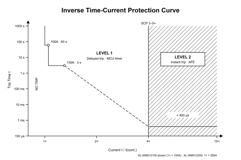
To clear transient spikes while protecting internal PCB copper traces, busbars, and switching elements, the BMS implements an inverse time-current curve with dual-stage overcurrent thresholds:
- Level 1 Overcurrent Protection (Software-Controlled Delay): Clears sustained moderate overloads. When discharge current breaches safe continuous limits, the MCU starts a firmware countdown timer. If the current draw remains elevated beyond the programmed delay window, the BMS interrupts the discharge path.
- Level 2 Overcurrent Protection (Fast Hardware Trip): Catches severe instantaneous current surges. An Analog Front-End (AFE) comparator pulls the gate low directly, bypassing MCU clock cycles entirely.
The hardware design of Haven Deer Grade A LiFePO4 battery modules reflects this dynamic current envelope:
Haven Deer AL-WM512100 (51.2V 100Ah / 5.12kWh Module)
- Continuous Charge/Discharge Current: 100A DC
- Level 1 Peak Discharge Current (Stage 1): 105A DC (Maximum duration: 60 seconds)
- Level 2 Peak Discharge Current (Stage 2): 130A DC (Maximum duration: 3 seconds)
Haven Deer AL-WM512200 (51.2V 200Ah / 10.24kWh Module)
- Continuous Charge/Discharge Current: 200A DC
- Level 1 Peak Discharge Current (Stage 1): 210A DC (Maximum duration: 60 seconds)
- Level 2 Peak Discharge Current (Stage 2): 260A DC (Maximum duration: 3 seconds)
3.2 Short-Circuit Protection (SCP) and Hardware MOSFET Switching
Firmware cannot interrupt dead shorts. Direct, low-impedance external faults dump thousands of amps within microseconds, demanding dedicated analog hardware trip stages:
- Short-Circuit Detection Threshold: Hardwired above peak inductive surges (typically 3x to 5x continuous rating).
- Hardware Trip Speed: Sub-millisecond cutoff (typically <200 to 400 microseconds) through the AFE sensing loop.
When shunt voltage spikes beyond the SCP limit, the AFE instantly drops gate drive to protect the switching FETs. This cuts the DC output path before fault energy damages copper traces or welds contact points.
Resetting a tripped SCP event requires disconnecting the external fault path, clearing line shorts, or cycling master battery power.
Common Mistake: Undersizing battery capacity relative to inverter surge ratings. A single 5.12kWh pack with a 100A continuous discharge rating provides roughly 5.12kW of continuous DC power at nominal voltage (Nominal Output = 51.2V × 100A = 5,120W). Pairing an undersized battery with a high-draw inverter trips overcurrent protection under heavy loads. Always size total parallel battery discharge current to exceed the maximum DC input draw of the inverter.
4. Thermal Safeguards and Environmental Operating Envelopes
Ambient temperature dictates LiFePO4 reaction kinetics. While LiFePO4 exhibits far higher thermal runaway thresholds than nickel-rich NMC or NCA chemistries, operating outside thermal limits accelerates degradation and triggers hardware lockouts.
4.1 Low-Temperature Charging Cutoff (0°C Protection Barrier)
Never charge standard LFP below freezing. Sub-zero temperatures choke lithium-ion diffusion across the electrolyte:
- Normal Operating Range: Lithium ions smoothly intercalate into the graphite lattice during normal charging cycles.
- Sub-zero Temperatures (< 0°C): Intercalation slows drastically, forcing metallic lithium to plate directly onto the graphite anode.
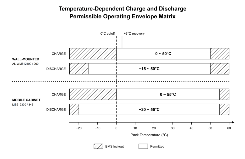
Lithium plating causes permanent capacity loss and dendrite-induced internal shorts. To protect the core chemistry during LiFePO4 low temperature charging, the BMS enforces an uncompromising Low-Temperature Charge Protection (LTCP) trip wire:
- Low-Temperature Charge Cutoff Trigger: 0°C (32°F)
- Low-Temperature Charge Recovery Threshold: +3°C (37.4°F)
If NTC sensors register pack temperature ≤ 0°C, the BMS blocks incoming PV and grid current. Cold discharge remains electrochemically viable down to rated limits, as de-intercalation does not trigger metallic plating.
4.2 High-Temperature Thermal Runaway Suppression (Charge/Discharge Limits)
Sustained heat breaks down the solid electrolyte interphase (SEI) layer and spikes cell impedance. The BMS positions multiple Negative Temperature Coefficient (NTC) thermistors directly against cell casings and high-current power stages to prevent hot-spot formation:
Wall-Mounted Enclosures (AL-WM512100 & AL-WM512200 / IP21 Rating)
- Charge Temperature Range: 0°C to 50°C
- Discharge Temperature Range: -15°C to 50°C
Floor-Standing Mobile off-grid solar batteries (MB512300 & MB512346 / IP22 Rating)
- Charge Temperature Range: 0°C to 55°C
- Discharge Temperature Range: -20°C to 55°C
If thermistors breach thermal ceilings, the BMS sheds charge and discharge paths instantly. Standard operation resumes once core cell thermistors cool down into the programmed hysteresis recovery band.
Common Mistake: Charging unheated outdoor LFP packs during freezing winter months. The BMS will lock out charging at 0°C, stranding available solar harvest. Always install indoor enclosures or integrate thermal heating pads in sub-zero regions.
5. Hardware vs. Software Protection Layers & Master-Slave Parallel Integration
Hardware must back up firmware. Modern BMS architectures combine software monitoring with autonomous analog circuits to prevent catastrophic single-point failures across single-pack and multi-cabinet setups.
5.1 Redundant Secondary Hardware Protection Layers
Microcontrollers can hang, drop loops, or freeze during voltage transients. To meet IEC 62619 battery functional safety standards when software execution stalls, advanced BMS platforms place an independent hardware supervisor alongside the primary MCU:
| Protection Feature | Primary Software Control (MCU Firmware) | Secondary Hardware Protection (AFE IC & Comparator) |
| Executing Hardware | Main Microcontroller Unit (MCU) | Dedicated Analog Front-End (AFE) IC |
| Response Speed | Milliseconds to seconds (firmware execution loops) | Sub-millisecond hardware trips (direct analog sensing) |
| Primary Tasks | Parameter telemetry, cell balancing, SoC calculation, CAN dispatch | Hard trips on overvoltage, dead shorts, and critical thermal runaways |
| Fault Reaction | Drops drive lines via software registers and logs fault codes | Directly pulls down MOSFET gates via internal hardware comparators |
| Failure Recovery | Automatic recovery once parameters return to hysteresis bands | Latches off until external fault clears or master DC breaker cycles |
If MCU firmware freezes during runaway, the autonomous AFE comparator drops gate drive directly. Hardware comparators operate completely out-of-band, providing a hard electrical ceiling that software bugs cannot override.
5.2 Master-Slave BMS Communication in Parallel Battery Arrays
Paralleling packs requires synchronized charge limits. When stacking multiple battery modules to expand bank capacity, individual BMS units must coordinate protection thresholds, fault propagation, and maximum allowable current in real time.
The master-slave BMS establishes an internal multidrop network governed by physical DIP switch addressing:
- Address Switch Assignment: Hardware DIP switches assign a unique node ID to each enclosure. Haven Deer parallel battery systems assign Address 01 to the Master unit, with subsequent packs configured sequentially as Slaves.
- Master BMS Function (Address 01): Unit 01 serves as the central data concentrator. It polls every slave pack over the internal bus for cell voltages, current, temperatures, and SoC metrics.
- Inverter Synchronization: The Master BMS sums the allowable charging current across all healthy modules and broadcasts the aggregate parameters directly to the hybrid inverter EMS via CAN.
- Safety Interlock Propagation: If a slave pack faults, its local switch isolates the module while the master BMS dynamically throttles system current over CAN to prevent the remaining healthy packs from absorbing sudden overcurrent shocks.
Commissioning Checklist: Parallel BMS Setup Verification
- Set unique DIP addresses sequentially (Pack 1 = 01 Master; remaining packs = sequential Slaves).
- Chain RJ45 communication jumpers between battery RS485/CAN link ports before applying bus power.
- Land the Master BMS CAN line onto the designated inverter battery-comms port using the correct vendor pinout (typically Pins 4/5 for CAN-H/CAN-L).
- Close individual battery breakers one by one to verify pre-charge sequencing before engaging the primary hybrid inverter DC isolator.
- Check the inverter LCD or Solar of Things App to confirm total reported ampere-hours (Ah) and closed-loop CAN handshake status.
6. Engineering Summary & Custom Energy Storage Sizing
Hardware cutoffs eliminate single-point failures. A robust BESS coordinates cell isolation, microsecond short-circuit trips, cold-charge interlocks, and master-slave comms into a unified safety matrix.
Off grid solar system sizing depends on matching battery continuous discharge limits directly to inverter draw and inductive motor surges. Pairing Haven Deer Grade A LiFePO4 packs (AL-WM wall-mount or MB floor-standing series) with ALL 486000 Pro or ALL 4812000 Pro hybrid inverters locks in native, closed-loop CAN coordination from initial power-up.
7. Frequently Asked Questions
What is the difference between primary software protection and secondary hardware protection in a BMS?
MCU firmware runs telemetry, balance routines, and programmable trip timers. The Analog Front-End (AFE) comparator provides autonomous, sub-millisecond hardware trips during dead shorts or critical overvoltage, operating independently if the MCU freezes.
Why does the BMS block battery charging below 0°C?
Sub-zero charging forces metallic lithium plating onto the graphite anode. This permanently cuts capacity and risks dendrite punctures. Discharging remains safe down to module limits (-15°C for wall-mount, -20°C for cabinets) because de-intercalation does not cause metallic plating.
Can a BMS recover a deeply discharged LiFePO₄ battery?
Yes. The BMS drops into sleep mode to halt parasitic drain. When paired with compatible hybrid inverters like the ALL Pro series, incoming PV or grid power sends an automated 0V activation pulse to wake the BMS and restore charging safely.
How does passive cell balancing work in a 51.2V LFP battery pack?
During constant-voltage charging, internal bleed resistors shunt bypass current around high cells to pull delta-V back into tolerance. Bleeding continues until cell spread drops within configured millivolt targets across all 16 cells.
What is the difference between continuous discharge current and peak discharge current?
Continuous current is the steady-state thermal limit the pack can sustain indefinitely (100A for 5.12kWh, 200A for 10.24kWh). Peak discharge current permits short-duration bursts (e.g., 130A for 3 seconds) to absorb motor locked-rotor inrush without tripping the protection circuit.
How does CAN bus communication improve battery protection over voltage-only sensing?
Closed-loop CAN replaces blind inverter voltage guessing with real-time BMS charge and discharge limits. The master BMS dynamically broadcasts allowable current limits based on cell temperatures and voltages, preventing nuisance inverter cutoffs.
What happens during a short circuit event on the battery terminals?
A dead short trips the AFE hardware comparator within sub-milliseconds, dropping gate drive before fault current vaporizes PCB traces. The solid-state switches latch open until the short is removed and the pack is power-cycled.
Why are 51.2V LFP batteries commonly used in residential energy storage applications?
51.2V falls safely within the Safety Extra Low Voltage (SELV) threshold under 60V DC. This eliminates high-voltage DC conduit requirements and hazardous arc-flash risks, making residential installation faster and substantially safer than 400V stacks.
How many battery packs can be safely connected in parallel with shared BMS communication?
Up to 6 packs can parallel reliably under master-slave addressing, scaling capacity to 61.44kWh without inducing RS485 polling lag. The master BMS aggregates data across all parallel nodes and feeds a single closed-loop telemetry stream to the inverter.
Does the BMS control the hybrid inverter’s operating mode (e.g., SUB vs. SBU)?
No. Safety hardware never dictates dispatch strategy. The BMS enforces boundary limits (current, voltage, temperature), while inverter EMS firmware directs power flows like Solar-Battery-Utility (SBU), Solar-Utility-Battery (SUB), or Time-of-Use.
What is the IP protection rating of Haven Deer battery enclosures?
Haven Deer wall-mounted enclosures (AL-WM series) carry an IP21 rating, while floor-standing mobile cabinets (MB series) feature IP22 protection. Both are engineered strictly for indoor installations, equipment rooms, and clean electrical closets.
How does low temperature affect the discharge capacity of LFP packs?
Cold electrolyte spikes internal cell impedance, causing steep under-load voltage sag and temporary capacity loss. The BMS allows discharge down to rated low limits, and available capacity returns completely to nominal as self-heating warms the cells.