Quick Technical Definition: A passive dry contact on a hybrid inverter is a volt-free relay (NO/NC/COM) driven by internal EMS logic, such as battery SoC or voltage thresholds. It sends an isolated contact closure signal to a generator ATS or two-wire remote start controller. This automates engine start-stop cycles without carrying line voltage through the terminals.
1. Fundamental Mechanics of Passive Dry Contact Signal Control
In remote microgrids and weak-grid environments, automated auxiliary power maintains uptime when solar yield drops or batteries deplete. Manual generator dispatch causes downtime and requires unnecessary truck rolls. Automated integration lets the hybrid inverter track battery status and trigger the backup generator directly.
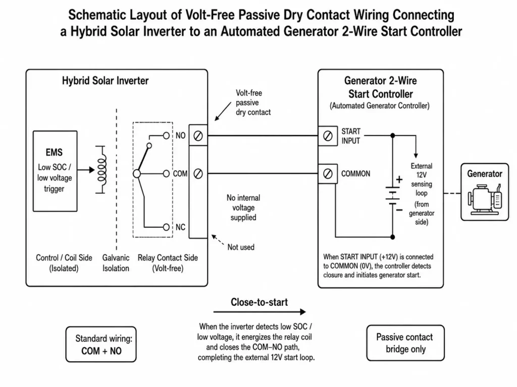
The passive dry contact relay drives this control loop. Physically isolating the inverter logic from the generator starter circuit ensures reliable field operation.
1.1 Volt-Free Switching Logic: Active vs. Passive Signals
Wiring active (wet) outputs into passive (dry) relay inputs is a common installation mistake.
- Active (Wet) Contacts: Supply internal voltage (12V or 24V DC) across output terminals. Connecting a wet signal to an isolated dry input damages control boards and protective components.
- Passive (Dry) Contacts: Function as an unpowered, isolated switch providing contact closure. The internal EMS energizes the relay coil to bridge or break physical contacts. The terminals output zero voltage or current.
The generator controller supplies its own low-voltage sensing loop. Closing the inverter dry contact completes this circuit without back-feeding voltage.
| Parameter | Active (Wet) Voltage Output | Passive (Dry) Contact Relay |
| Voltage Source | Internal (Supplies 12V/24V DC from inverter) | External / Volt-Free (Switch acts purely as contact bridge) |
| Galvanic Isolation | Low / Variable | Complete Physical Isolation (Relay isolated from power electronics) |
| Compatibility | Limited to matching voltage inputs | Compatible with most 2-wire start ATS or generator control modules |
| Risk of Hardware Damage | High (Back-feed voltage can damage control boards) | Reduced risk (Isolated dry terminals prevent voltage back-feeding into inverter circuits) |
1.2 Contact States: Normally Open (NO), Normally Closed (NC), and Common (COM)
A standard inverter dry contact terminal block provides three connection points:
- Common (COM): The shared reference terminal for the generator control loop.
- Normally Open (NO): Disconnected from COM by default. When EMS conditions trigger auto-start, the relay energizes and closes the COM-to-NO circuit.
- Normally Closed (NC): Connected to COM by default. Triggering auto-start opens the COM-to-NC circuit.
Installers wire COM and NO to create a standard close-to-start loop for generator ATS panels.
2. EMS Control Logic & Trigger Threshold Calibration
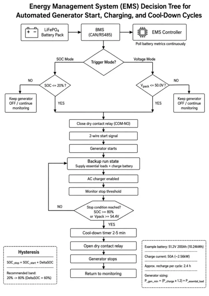
The EMS handles decision logic; the physical relay executes the switch. By tracking battery status, the EMS determines exact relay closure and opening timing.
2.1 SOC-Based vs. Voltage-Based Trigger Logic
Proper trigger calibration prevents short-cycling and protects LiFePO4 pack health.
+-------------------------------------------------------------------+
|                   EMS DRIVER CONTROL PIPELINE                     |
|                                                                   |
|  [LiFePO4 Cells] ---> [BMS (CAN/RS485)] ---> [EMS Controller]     |
|                                             |                     |
|                         +-------------------+                     |
|                         |                                         |
|                  [Check Battery Metrics]                          |
|                         |                                         |
|          +--------------+--------------+                          |
|          |                             |                          |
|   (SOC Mode Active)            (Voltage Mode)                     |
|          |                             |                          |
| Is SOC <= SOC_start?          Is Vpack <= V_start?                |
|    (e.g., <= 20%)                (e.g., <= 50V)                   |
|          |                             |                          |
|          +--------------+--------------+                          |
|                         |                                         |
|                       [YES]                                       |
|                         |                                         |
|             [Energize Relay (Close COM-NO)]                       |
|                         |                                         |
|              [Generator Auto-Starts]                              |
+-------------------------------------------------------------------+
- Closed-Loop SoC Triggering (Recommended): Closed-loop CAN or RS485 comms feed real-time SoC data from the BMS directly to the EMS. This delivers far more precise generator cycling than voltage sensing.
- Open-Loop Voltage Triggering (Fallback): Without BMS comms, the EMS relies on terminal voltage. However, LiFePO4's flat discharge curve means heavy load spikes cause transient voltage sags, triggering false generator starts.
| Parameter | SOC-Based Triggering (Recommended) | Voltage-Based Triggering (Fallback) |
| Primary Metric | BMS Reported State of Charge (%) | Measured Battery Terminal Voltage (V) |
| LiFePO4 Accuracy | High (Accurate across flat discharge curve) | Lower (Affected by transient voltage changes under high loads) |
| Prerequisites | Closed-loop CAN/RS485 BMS Communication | Open-loop / Legacy battery configuration |
| Recommended Setting | Example: Start: 20% SOC / Stop: 80% SOC | Example: Start: 50.0V / Stop: 54.4V (for 51.2V nominal LFP) |
Learn more about Setting Dry Contact Trigger Thresholds (SOC % vs. Voltage).
2.2 Preventing Short-Cycling: Hysteresis Band Engineering
Setting a wide hysteresis band (ΔSoC or ΔVoltage) stops generator short-cycling.
The formula defining the trigger state machine is:
SOC_stop = SOC_start + ΔSOC
Where:
- SOC_start: The lower state of charge threshold where the dry contact closes (e.g., 20%).
- SOC_stop: The upper state of charge threshold where the dry contact reopens (e.g., 80%).
- ΔSOC: The required generator recovery window between start and stop thresholds.
Engineering Calculation Example:
Consider an off-grid installation equipped with a 51.2V 200Ah (10.24kWh) LiFePO4 battery module connected to a 6kW hybrid inverter.
- Parameter Calibration: Set SOC_start to 20% and SOC_stop to 80% (ΔSOC = 60%) for the recovery window.
- Usable Capacity Requirement: 10.24 kWh × 0.60 = 6.144 kWh to replenish per cycle.
- Inverter Charge Profile: With a configured AC charge limit of 50A at 51.2V nominal (2.56 kW DC charge power), calculate replenishment runtime:
Charge Time = 6.144 kWh / 2.56 kW = 2.4 Hours
A continuous 2.4-hour runtime stabilizes battery recovery and prevents short-cycling.
Generator Capacity Reference:
Size the generator based on combined battery charging demand and baseline critical loads:
P_gen_reference = (P_inv_charge_max × 1.2) + P_essential_load
Where:
- P_gen_reference: Reference generator output requirement (kW).
- P_inv_charge_max: Maximum DC battery charging power converted to AC input power (kW).
- P_essential_load: Continuous baseline electrical load of the site during backup operation (kW).
3. Electrical Interface & Generator ATS Wiring Schematics
Wiring the inverter dry contact to the generator controller requires correct cable selection, noise isolation, and strict adherence to contact ratings.
3.1 Connecting to Two-Wire Remote Start Controllers & ATS Units
Most diesel and gas generators with digital controllers support standard two-wire remote start inputs.
- Wire Selection: Use low-voltage signal cable for the controller interface. Use shielded twisted-pair wire if specified by the manufacturer. Route signal cables away from high-voltage AC/DC lines to prevent electromagnetic interference.
- Terminal Termination: Wire the inverter COM and NO terminals directly to the generator's two-wire remote start terminals following the manufacturer schematic.
- Relay Contact Limitations: Standard inverter dry contacts handle low-current control signals, typically rated up to 250V AC / 3A or 30V DC / 3A.
CRITICAL WARNING: Never wire dry contacts directly to high-current starter or fuel solenoids. Overcurrent burns out internal relay contacts. Always install an interposing relay when switching heavy inductive loads.
3.2 Shared AC Input Terminal Constraints: Grid vs. Generator Input
A key hardware constraint in hybrid inverters is the shared AC input terminal. The unit uses a single AC port for either grid power or generator power.
     +-----------------------+
     |  Utility Grid (AC 1)  |
     +-----------+-----------+
                 |
                 v
     +-----------------------+
     | External Manual/Auto  |
     | Transfer Switch (ATS) |
     +-----------+-----------+
                 |
                 v
     +-----------------------+
     |  Generator (AC 2)     |
     +-----------+-----------+
                 |
                 v
+-----------------------------------------------------------+
|  [Hybrid Inverter AC Input Terminal]                      |
|                                                           |
|  * WARNING: Utility grid and generator outputs must not   |
|    be connected simultaneously without an interlocked     |
|    transfer mechanism.                                    |
+-----------------------------------------------------------+
Single-input inverters cannot accept grid and generator AC power simultaneously without an external transfer switch.
| Configuration Scenario | System Topology Requirements | Operational Protocol |
| Pure Off-Grid (No Grid) | Generator AC output connected directly to inverter AC input | Inverter dry contact triggers generator auto-start. |
| Weak-Grid + Generator Backup | External interlocked manual or automatic transfer switch (ATS) required | ATS selects utility grid or generator power before entering the inverter AC input terminal. |
4. Field Engineering & Safety Protocols (IEC Compliance)
Automating generator control requires strict safety compliance, proper grounding, and clean AC power before inverter integration.
4.1 Frequency & Voltage Drift Mitigation
Small generators suffer voltage and frequency drift under sudden load spikes. Hybrid inverter chargers require clean AC input to lock phase.
- Acceptable Input Window: Generator voltage and frequency must stay strictly within the inverter's AC input limits.
- Frequency Sensitivity: Heavy inductive surges cause engine speed droop and frequency instability. Unstable AC sources force the EMS to trip off. Set generator governor parameters per manufacturer specifications.
4.2 Neutral-Earth Bonding & Isolation Protocols
Field wiring must comply with IEC 62109-1 and IEC 62109-2 for inverter isolation, grounding, and protection.
- System Bonding: Neutral-to-earth bonding must remain compliant with local code during grid-to-island transitions under generator power.
- Floating Neutrals: Many portable generators ship with a floating neutral. Verify local codes and bonding requirements before tying the generator into the inverter AC bus.
For more details, see our IEC 62109-1 / IEC 62109-2 Compliance Guide.
4.3 First-Time Installer Dry Contact Commissioning Checklist
- Verify dry contact signal cables connect to COM and NO for standard close-to-start logic.
- Ground control cable shielding at one end per generator specs to reject noise.
- Measure dry contact loop current to keep it below relay ratings.
- Establish closed-loop CAN/RS485 communication between inverter EMS and battery BMS for SoC-based triggering.
- Program SOC_start (e.g., 20%) and SOC_stop (e.g., 80%) thresholds in the EMS menu.
- Force dry contact closure manually through the commissioning app to test relay response.
- Verify the generator controller executes configured warm-up and cool-down cycles upon receiving signal.
- Mechanically interlock grid and generator AC feeds before connecting to the inverter input terminal.
5. Haven Deer Hybrid Inverter Dry Contact Integration Framework
Haven Deer hybrid inverters feature factory-installed passive dry contact interfaces that link inverter, battery, BMS, and EMS logic. The system automates generator start-stop control during grid outages or low solar yield.
5.1 On-Board Relay Specifications
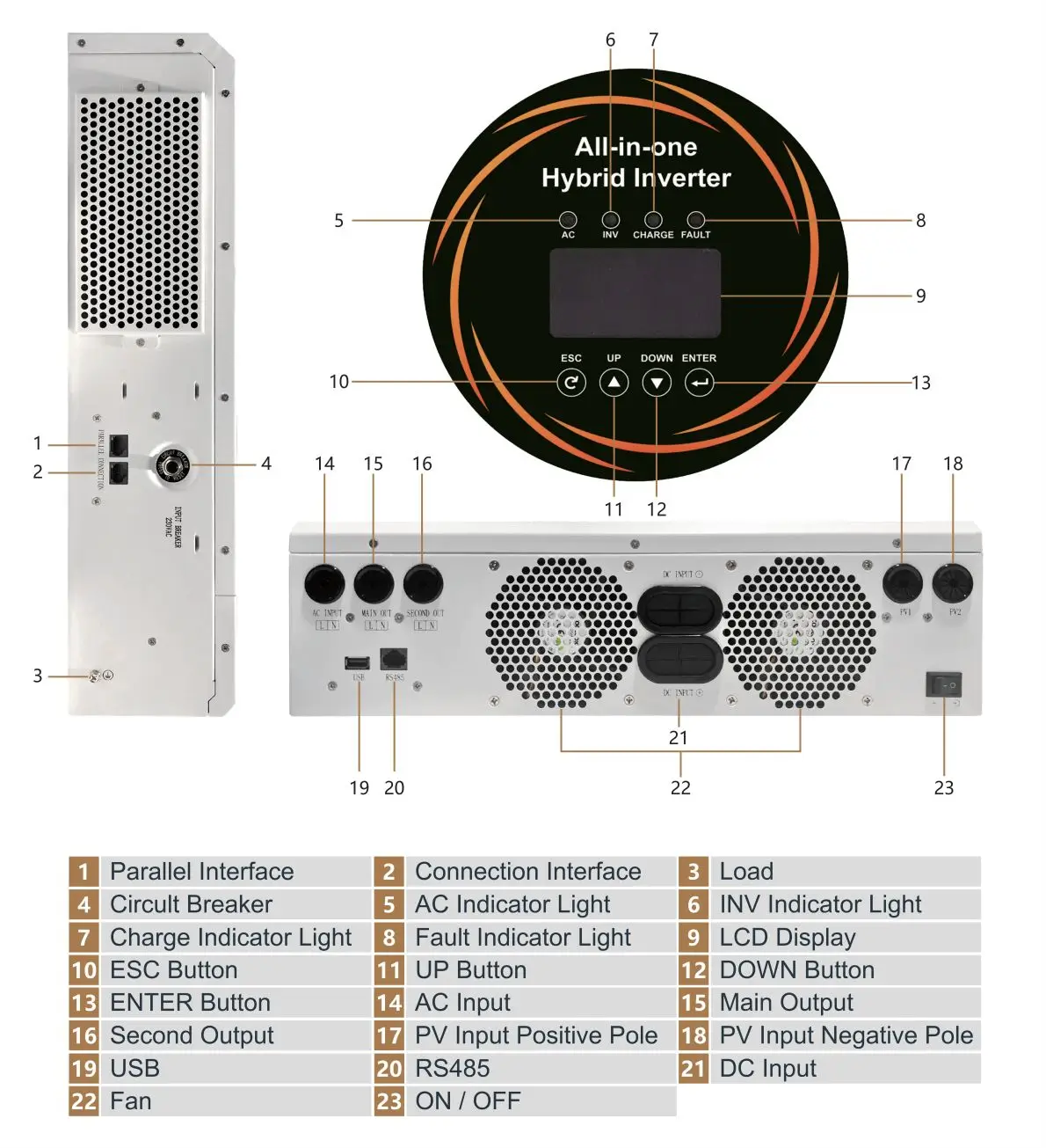
Both Haven Deer ALL 486000 Pro (6kW) and ALL 4812000 Pro (12kW) models include onboard dry contact terminals to drive external generator controllers and ATS units.
| Inverter Hardware Spec | Haven Deer ALL 486000 Pro | Haven Deer ALL 4812000 Pro |
| Rated Output Power | 6,000W | 12,000W |
| Surge Capacity | 12,000VA (5 seconds) | 22,000VA |
| Integrated Dry Contact Relay | Yes (NC, COM, NO Terminals) | Yes (NC, COM, NO Terminals) |
| Relay Contact Voltage/Current | 250V AC / 3A ; 30V DC / 3A | 250V AC / 3A ; 30V DC / 3A |
| BMS Communication | CAN / RS485 / RS232 | CAN / RS485 / RS232 |
| MPPT Architecture | Single MPPT (120–500V DC) | Dual Independent MPPT (60–500V DC) |
| UPS Transfer Capability | 10ms (Sensitive Loads) / 20ms (Home Appliances) | 10ms (Sensitive Loads) / 20ms (Home Appliances) |
| Dual AC Output (Smart Load) | Supported | Supported |
5.2 Automated System Commissioning Protocol
Commissioning Haven Deer inverters with Grade A LiFePO4 modules (such as the AL-WM512200 10.24kWh wall-mount or MB512300 15.0kWh cabinet battery) follows a four-step sequence:
- Closed-Loop Communication Setup: Wire the CAN/RS485 bus between the battery Master BMS and inverter to enable real-time telemetry.
- EMS Parameter Selection: Access the commissioning app and enable SoC-based generator control mode.
- Threshold Configuration: Set generator auto-start (e.g., 20% SoC) and auto-stop (e.g., 80% SoC) limits in the EMS menu.
- Automated Microgrid Orchestration: The inverter coordinates solar PV, battery storage, and generator dispatch automatically. This eliminates manual site intervention during low-SoC events.
6. Frequently Asked Questions
What is a passive dry contact on a hybrid solar inverter?
A passive dry contact is an integrated, volt-free relay switch (offering NO, NC, and COM terminals) that opens or closes based on internal inverter EMS logic. It sends an unpowered remote start signal to an external generator controller without supplying voltage across the terminals.
How does the inverter signal the generator to start auto-charging?
When battery SoC or voltage drops below the programmed lower limit, the EMS energizes the dry contact relay. This closes the circuit between COM and NO, completing the generator ATS remote-start sense loop.
Can I connect my generator and utility grid to the hybrid inverter at the same time?
No. Haven Deer hybrid inverters use a single shared AC input port. Grid and generator AC power must route through an external interlocked manual or automatic transfer switch (ATS) before entering the inverter input.
Why is SOC-based triggering superior to voltage-based triggering for LiFePO4 batteries?
LiFePO4 batteries exhibit an extremely flat discharge voltage curve between 20% and 80% SOC. Voltage-based monitoring can cause false generator triggers during brief surge load drops. Closed-loop BMS SOC tracking via CAN/RS485 ensures precise, load-independent fuel scheduling.
What relay contact voltage and current ratings are supported?
Haven Deer dry contacts support up to 250V AC / 3A or 30V DC / 3A. High-current starter solenoids exceeding 3A must be triggered through an intermediate external industrial contactor or relay module.
Will the inverter automatically turn off the generator when charging is complete?
Yes. Once the battery bank reaches the programmed upper SOC threshold (e.g., 80% or 100%), the EMS re-opens the COM-NO dry contact relay. This breaks the remote-start circuit, signaling the generator to execute its cool-down and shutdown sequence.
What happens if the generator runs out of fuel during auto-charge?
If the generator engine stalls, the inverter EMS detects a loss of AC input voltage and frequency. The EMS isolates the AC input port and switches back to battery power within 10ms to 20ms. It then triggers an AC fault alarm on the app.
Do I need a 2-wire or 3-wire generator start module for dry contact integration?
Standard inverter dry contacts interface natively with 2-wire auto-start controllers. 3-wire key-start generators require an intermediate 3-wire to 2-wire conversion adapter relay module.
Can the dry contact signal trigger non-generator loads like Smart Loads?
Dry contacts are optimized for low-current control signaling. To manage non-essential AC loads, Haven Deer inverters use built-in Dual AC Output terminals for automatic Smart Load shedding.
Does Haven Deer support zero-export mode while charging from a generator?
Zero-export controls apply specifically to grid-interactive systems. When connected to a generator AC input, the inverter operates in off-grid mode, utilizing generator AC power exclusively for local loads and battery charging.
Are Haven Deer dry contact control systems compliant with IEC safety standards?
Yes. All Haven Deer inverter control interfaces comply with IEC 62109-1 and IEC 62109-2 standards for electrical safety and galvanic isolation in photovoltaic power systems.
7. Need a Custom Off-Grid Microgrid Architecture for Your Project?
Haven Deer application engineers review single-line diagrams (SLDs), map generator dry contact control logic, and size battery storage for off-grid BESS projects.
Submit your project details for direct application engineering support.