Quick Answer:Sizing an off-grid Solar Energy Storage System (Solar ESS) kit requires a five-step engineering process: (1) analyzing daily energy consumption and peak load demand; (2) calculating battery capacity based on autonomy days, Depth of Discharge (DoD), inverter efficiency, and temperature conditions; (3) sizing the PV array according to energy demand, Peak Sun Hours (PSH), MPPT voltage limits, and cold-weather Voc rise; (4) selecting a Hybrid Inverter Energy Hub based on continuous power, surge capability, and PV input requirements; and (5) integrating auxiliary generator backup with automated Dry Contact control logic.
1. Core Engineering Principles of Off-Grid System Sizing
Designing an off-grid Solar Energy Storage System (Solar ESS) is fundamentally different from sizing a grid-tied solar system. In a grid-tied configuration, the utility grid provides external energy balancing by absorbing excess photovoltaic (PV) generation and supplying deficit power when solar production is insufficient. In a modern off-grid Solar ESS architecture, the system operates as an independent microgrid where PV generation, battery storage, and auxiliary generation must be coordinated to maintain continuous power availability. Every kilowatt-hour consumed by the loads must be generated, stored, or supplied through the integrated energy management architecture.
A complete off-grid Solar ESS kit consists of four interconnected subsystems:
- Photovoltaic Generation: Converts solar irradiance into DC power.
- Energy Hub (Hybrid Inverter): Converts DC and AC power bidirectionally, manages battery charging and discharging processes, and coordinates energy flow between PV, battery storage, grid, generator, and electrical loads through the EMS.
- Energy Storage (Battery Bank): Stores electrical energy through Grade A Lithium Iron Phosphate (LiFePO4) battery cells and supplies power to electrical loads when PV generation is unavailable or insufficient.
- Auxiliary Input (Grid/Generator): Provides supplementary AC power during extended periods of insufficient solar generation, with generator integration controlled through the hybrid inverter’s Dry Contact automation function.
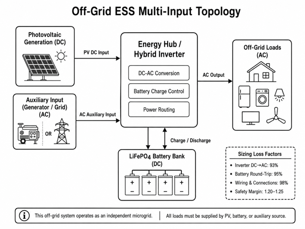
When sizing these integrated components, engineers must account for energy losses across every stage of the system. Practical ESS design must consider inverter conversion efficiency, battery round-trip efficiency, and cable voltage losses. Ignoring these factors can result in insufficient battery autonomy, reduced solar availability, and unexpected load shedding during real-world operation.
| System Stage / Element | Nominal Engineering Efficiency | Sizing Impact & Mitigation |
|---|---|---|
| Inverter Conversion (DC to AC) | 93% efficiency | Inverter conversion losses increase the required battery output to supply AC loads. Load calculations should account for approximately 93% inverter efficiency when converting between DC battery energy and AC load demand. |
| LiFePO4 Battery Round-Trip | 95% efficiency | Energy losses during battery charging and discharging require efficiency factors to be included when calculating required PV generation and battery capacity. |
| Wiring & Connections (I²R) | 98% efficiency | Voltage drop across DC cables dissipates energy as heat. Cable cross-sections should be selected to maintain voltage drop below 1%. |
| System Safety Margin Factor | 1.20 to 1.25 multiplier | Added to PV array sizing to compensate for seasonal dust accumulation, panel aging, and environmental variations. |
System reliability and operational safety always take priority over short-term performance specifications. An engineering-first approach requires balancing continuous power capacity, surge capability, battery autonomy, thermal stability, and compliance with international safety standards such as IEC 62109-1, IEC 62109-2, UL 1741, and IEC 61000-6-1/IEC 61000-6-3 across all operating environments.
2. Step 1: Electrical Load Profile & Daily Energy Consumption Analysis
The foundation of every off-grid system calculation is an accurate electrical load profile. Sizing an off-grid Solar ESS kit requires analyzing actual load characteristics rather than relying only on monthly utility bills or estimated consumption values. Engineers must evaluate each electrical device based on operating power, daily runtime, load type, and startup characteristics to determine the required battery capacity and inverter rating.
2.1 Resistive vs. Inductive Loads
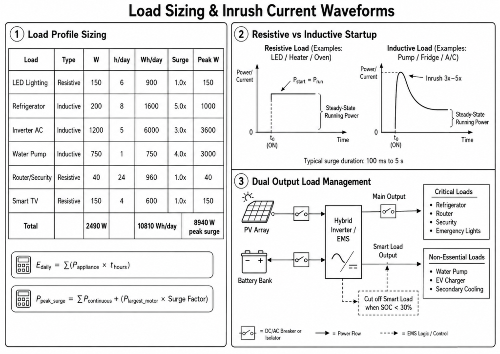
- Resistive Loads: Equipment such as LED lighting, resistive heaters, and electric ovens convert electrical current directly into heat or light. Power consumption is linear and predictable. Running power equals starting power:
P_start = P_run
- Inductive Loads: Devices containing electric motors, compressors, or transformers—such as air conditioners, deep well pumps, refrigerators, and power tools—require higher startup current to establish the initial electromagnetic field. This creates a short-duration inrush surge that can reach approximately 3× to 5× the rated continuous running power during startup, requiring sufficient inverter surge capability.
To establish total daily energy consumption (E_daily) in watt-hours (Wh) and required inverter peak surge capacity (P_peak_surge) in watts (W), apply the following formulas:
E_daily = Sum(P_appliance × t_hours)
P_peak_surge = P_continuous_loads + (P_largest_motor × Surge_Factor)
Where:
- P_appliance = Rated running power of each device in watts.
- t_hours = Operating duration of each device per day in hours.
- P_largest_motor = Rated running power of the largest inductive motor load.
- Surge_Factor = Startup surge multiplier for inductive motor loads (typically 3.0 to 5.0).
2.2 Sample Residential Load Profile Sizing Table
| Appliance / Electrical Load | Load Type | Rated Watts (W) | Operating Hours (h/day) | Daily Energy (Wh/day) | Surge Multiplier | Peak Surge Power (W) |
|---|---|---|---|---|---|---|
| LED Lighting Array | Resistive | 150 W | 6.0 h | 900 Wh | 1.0× | 150 W |
| Refrigerator / Freezer | Inductive | 200 W | 8.0 h (duty cycle) | 1,600 Wh | 5.0× | 1,000 W |
| Inverter Air Conditioner | Inductive | 1,200 W | 5.0 h | 6,000 Wh | 3.0× | 3,600 W |
| Water Submersible Pump | Inductive | 750 W | 1.0 h | 750 Wh | 4.0× | 3,000 W |
| Wi-Fi Router & Security | Resistive | 40 W | 24.0 h | 960 Wh | 1.0× | 40 W |
| Smart TV & Entertainment | Resistive | 150 W | 4.0 h | 600 Wh | 1.0× | 150 W |
| Total Load Profile Summary | — | 2,490 W | — | 10,810 Wh/day | — | 8,940 W |
Engineering Tip: When profiling inductive loads, do not rely solely on nameplate running wattage. Single-phase motor loads can require approximately 3× to 5× their rated running power during startup. If inverter surge capability is not properly matched to these transient demands, overload protection may activate even when continuous load power remains within the inverter rating.
2.3 Dual Output Load Management (Main vs. Smart Load)
Modern hybrid inverters feature Dual Output architecture to prioritize critical loads and manage battery energy availability during extended low-solar periods. Loads should be physically separated at the distribution board:
- Main Output (Critical Loads): Connected to essential infrastructure such as refrigerators, communication equipment, security systems, and emergency lighting. Power flows continuously from the battery bank during grid failure.
- Second Output (Smart Load): Connected to non-essential loads such as water pumps, EV chargers, or secondary cooling units. The Energy Management System (EMS) can disconnect the Smart Load output when battery State of Charge (SOC) reaches a configured protection threshold, preserving available battery energy for critical circuits connected to the Main Output.
3. Step 2: Battery Capacity Sizing & Days of Autonomy Calculation
Once total daily energy consumption (E_daily) is defined, the battery storage bank must be sized to provide continuous power during nighttime periods, low-solar conditions, and extended weather events.
3.1 Depth of Discharge (DoD) & Cycle Life
Lithium Iron Phosphate (LiFePO4) chemistry provides superior thermal stability and cycle life compared with traditional lead-acid chemistries. However, operating parameters directly influence long-term service life:
- 90% Depth of Discharge: Provides maximum usable capacity per cycle but reduces expected cycle life to ≥6,000 cycles under standard operating conditions.
- 80% Depth of Discharge: Represents the recommended engineering baseline, providing ≥10,000 cycles to 80% End of Life (EOL) under standard conditions. Operating at 80% DoD balances usable energy availability with long-term battery service life.
3.2 Days of Autonomy
Autonomy refers to the number of days the battery bank can supply required loads without any energy input from solar panels or auxiliary generators. Standard residential autonomy targets range from 1.0 to 1.5 days. Remote industrial or agricultural sites may require 2.0 to 3.0 days.
3.3 Required Battery Capacity Formula
E_bat_req = (E_daily × Days_autonomy) ÷ (DoD × η_inv × η_temp)
Where:
- E_daily = Daily energy demand (kWh/day).
- Days_autonomy = Required backup duration without PV or generator input (e.g., 1.5 days).
- DoD = Depth of Discharge limit (0.80 for 80% DoD).
- η_inv = Battery-to-AC conversion efficiency of the inverter (0.93).
- η_temp = Temperature correction factor (1.0 at 25°C; 0.85–0.90 under sub-zero operating conditions).
3.4 Battery Technology Comparison: Grade A LiFePO4 vs. Lead-Acid
| Technical Parameter | Grade A LiFePO4 Module | Traditional Lead-Acid (AGM/GEL) | Engineering Impact |
|---|---|---|---|
| Recommended DoD | 80% (Daily cycling) / 90% Max | 50% Maximum | LiFePO4 provides higher usable energy per rated Ah. |
| Cycle Life (EOL 80%) | ≥6,000 to 10,000 cycles | 500 to 1,500 cycles | LiFePO4 provides significantly longer service life under proper operating conditions. |
| Round-Trip Efficiency | ~95% | ~75%–80% | Lower energy loss improves overall system efficiency. |
| Temperature Sensitivity | Charge: 0°C to 50°C / Discharge: -15°C to 50°C | Derates rapidly below 20°C | Integrated BMS prevents charging below 0°C to reduce lithium plating risk. |
| Parallel Expansion | Up to 6 units recommended (master-slave CAN/RS485) | High string imbalance risk | Modular LiFePO4 packs support scalable energy storage expansion. |
3.5 Haven Deer Modular LiFePO4 Battery Options
To simplify site installation, Haven Deer provides factory-matched 51.2V Grade A LiFePO4 battery architectures based on 16 series-connected (16S) prismatic cells with integrated BMS protection and parallel expansion capability.
Wall-Mounted Series
- AL-WM512100: 51.2V 100Ah / 5.12 kWh
- AL-WM512200: 51.2V 200Ah / 10.24 kWh
Floor-Standing Mobile Cabinet Series
- MB512300: 51.2V 300Ah / 15.0 kWh
- MB512346: 51.2V 346Ah / 18.0 kWh
- AL-WM512100 Wall-Mounted (5.12 kWh): Rated at 51.2V 100Ah (102Ah nominal). Weight: 45.5 kg. Continuous discharge: 100A. Ideal for compact residential installations.
- AL-WM512200 Wall-Mounted (10.24 kWh): Rated at 51.2V 200Ah (206Ah nominal). Weight: 102 kg. Continuous discharge: 200A. Wall mounting requires structural load verification.
- MB512300 Mobile Cabinet (15.0 kWh): Floor-standing industrial enclosure with heavy-duty casters. Rated at 51.2V 300Ah. Continuous discharge: 200A. Protection rating: IP22.
- MB512346 Mobile Cabinet (18.0 kWh): High-density floor cabinet. Rated at 51.2V 346Ah. Continuous discharge: 200A. Weight: 163 kg. Suitable for commercial and microgrid sites.
Common Mistake: Do not connect 51.2V LiFePO4 battery modules in series to increase system voltage. Series connection is not supported because it interferes with the 16S BMS cell monitoring and balancing architecture. To increase storage capacity, connect identical 51.2V battery modules in parallel with closed-loop CAN or RS485 master-slave communication, supporting up to 6 parallel units.
4. Step 3: Photovoltaic (PV) Array Sizing & MPPT Voltage Matching
The photovoltaic array must generate sufficient energy during available daylight hours to supply daytime loads, compensate for system losses, and recharge the battery bank to the required State of Charge (SOC) after daily consumption.
4.1 Peak Sun Hours (PSH)
Solar irradiance varies by geographical region and season. Sizing calculations must use the site’s worst-case seasonal average Peak Sun Hours (PSH)—typically winter values—rather than summer peaks. PSH represents the equivalent hours per day when solar irradiance averages 1,000 W/m².
4.2 Required PV Array Peak Power Formula
P_PV_peak = (E_daily × SF_losses) ÷ (PSH × η_system)
Where:
- E_daily = Daily energy demand (Wh/day).
- SF_losses = PV safety oversizing multiplier (1.20 to 1.25) to compensate for cable losses, panel aging, dust accumulation, and environmental variations.
- PSH = Worst-case seasonal Peak Sun Hours (h/day).
- η_system = Overall PV system efficiency factor (approximately 0.85 to 0.90 including MPPT tracking, wiring losses, and battery charging losses).
4.3 MPPT Voltage Range & String Configuration
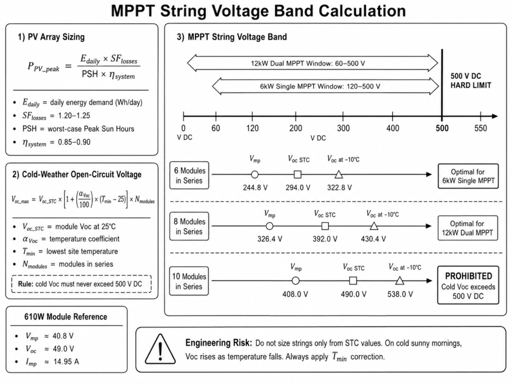
Matching PV string voltage to the Maximum Power Point Tracking (MPPT) operating window of the hybrid inverter is critical for stable energy harvesting. The operating voltage must remain within the inverter MPPT tracking range, while the cold-weather maximum Open-Circuit Voltage (V_oc_max) must never exceed the inverter’s 500 V DC absolute input limit.
4.4 Cold-Weather Open-Circuit Voltage Formula
V_oc_max = V_oc_STC × [1 + (α_Voc ÷ 100) × (T_min – 25)] × N_modules
Where:
- V_oc_STC = Module open-circuit voltage at Standard Test Conditions (25°C).
- α_Voc = PV module temperature coefficient of Voc (%/°C, typically negative, for example -0.28%/°C).
- T_min = Lowest historical temperature at the installation site (°C).
- N_modules = Number of PV modules connected in series within one string.
4.5 PV Module Compatibility: Grade A 610W Monocrystalline Panels
Haven Deer 610W monocrystalline PV modules operate at approximately V_mp = 40.8V, V_oc = 49.0V, and I_mp = 14.95A under Standard Test Conditions (STC).
| String Configuration (610W Modules) | Nominal String V_mp (25°C) | String V_oc at STC (25°C) | String V_oc at -10°C (T_min) | MPPT Compatibility Status |
|---|---|---|---|---|
| 6 Modules in Series | 244.8 V DC | 294.0 V DC | 322.8 V DC | Optimal for 6kW Single MPPT (120–500V range) |
| 8 Modules in Series | 326.4 V DC | 392.0 V DC | 430.4 V DC | Optimal for 12kW Dual MPPT (60–500V range) |
| 10 Modules in Series | 408.0 V DC | 490.0 V DC | 538.0 V DC | PROHIBITED: Cold-weather V_oc exceeds the 500 V DC maximum input limit! |
Engineering Risk: Designing PV strings close to the 500 V DC limit using only STC (25°C) values can cause inverter overvoltage faults during cold winter conditions. As PV module temperature decreases, Voc increases due to the negative temperature coefficient effect. Always apply the site’s minimum temperature correction when calculating maximum string voltage.
5. Step 4: Hybrid Inverter Capacity & Surge Load Matching
The hybrid inverter serves as the system’s central Energy Hub. It manages bidirectional power conversion between PV, battery, AC sources, and loads, coordinates BMS communication through CAN/RS485 protocols, executes EMS energy management strategies, and provides fast transfer switching during grid outages.
  [Solar PV Array]            [Grid / AC Generator]
           │                              │
           ▼                              ▼
           └──────────────┬───────────────┘
                          ▼
            [Hybrid Inverter / Energy Hub]
                          │
           ┌──────────────┴──────────────┐
           ▼                             ▼
 [LiFePO4 Battery Bank]          [Main & Smart Loads]
    (CAN/RS485 BMS)              (EMS Load Management)
Inverter selection must satisfy two separate load criteria:
- Continuous Power Rating (P_inv_cont): Must be equal to or greater than the maximum simultaneous continuous AC power demand of all connected loads.
- Surge Power Rating (P_inv_surge): Must be equal to or greater than the maximum instantaneous power demand created by inductive motor startup currents.
5.1 Sizing Criteria Summary
P_inv_cont ≥ P_total_running_loads
P_inv_surge ≥ P_total_running_loads + P_largest_motor_surge
5.2 Haven Deer Hybrid Solar Inverter Comparison
| Engineering Feature | ALL 486000 Pro | ALL 4812000 Pro |
|---|---|---|
| Rated AC Output Power | 6,000W (Continuous) | 12,000W / 12,000VA (Continuous) |
| Peak Surge Rating | 12,000VA (5 seconds) | 22,000VA (5 seconds) |
| Battery System Voltage | 48V DC nominal (40.0–60.0V DC operating range) | 48V DC nominal (40.0–60.0V DC operating range) |
| MPPT Trackers / Channels | 1 Single MPPT Tracker | Dual Independent MPPT Trackers |
| Max PV Input Power | 9,000W total | 15,000W total (7,500W × 2 MPPT channels) |
| MPPT Operating Voltage Range | 120–500V DC (300–400V DC optimal) | 60–500V DC |
| Max PV Open Circuit Voltage (V_oc) | 500V DC | 500V DC |
| Max PV Input Current | 27A | 27A × 2 channels |
| Max Combined Charging Current | 100A (Solar + AC) | 160A (Solar + AC) |
| UPS Transfer Time | 10ms (Personal Computer) / 20ms (Home) | 10ms (Personal Computer) / 20ms (Home) |
| Parallel Expansion Limit | Up to 6 units in parallel (36kW maximum system output) | Up to 6 units in parallel operation supported |
| Protection Rating & Weight | IP21 / 10.5kg | IP21 / 16.2kg |
5.3 Advantages of Dual Independent MPPT (12 kW Model)
For complex installations, the dual independent MPPT channels on the ALL 4812000 Pro provide distinct engineering benefits:
- Multi-Aspect Roofs: Enables East-facing and West-facing PV strings to operate on separate MPPT channels without forcing identical string orientation or operating conditions.
- Partial Shading Isolation: Separates PV strings into independent MPPT channels, reducing the impact of shading conditions on other unaffected strings.
- Mixed String Configurations: Allows PV strings with different module quantities or installation orientations to be managed independently through separate MPPT trackers.
6. Step 5: Auxiliary Generator Integration & Dry Contact Automation
In off-grid microgrids, prolonged periods of low solar irradiance can reduce PV energy availability for multiple days. Integrating a backup generator through the hybrid inverter provides automated energy support when battery SOC reaches configured protection thresholds.
6.1 Shared AC Input Terminal Constraint
Haven Deer hybrid inverters utilize a shared AC input terminal that supports either utility grid input or generator input for backup power operation.
Important Engineering Constraint: The shared AC input terminal supports only one active AC source at a time. Utility Grid and AC Generator inputs cannot operate simultaneously through the same terminal without an external transfer switching solution.
6.2 Dry Contact Auto-Start Automation
Automation is achieved through the inverter’s built-in passive Dry Contact relay interface. The inverter EMS monitors battery parameters such as SOC or voltage and sends a voltage-free relay signal to the generator’s automatic start controller:
 [Battery SOC Drops Below Start Threshold (<20% SOC / Low Voltage Limit)]
                                     │
                                     ▼
                  [EMS Closes Inverter Dry Contact Relay]
                                     │
                                     ▼
             [Signal Triggers Auto-Start Generator Controller]
                                     │
                                     ▼
                 [Generator Powers Inverter AC Input Port]
                                     │
                                     ▼
               [Inverter Recharges Battery & Powers AC Loads]
                                     │
                                     ▼
[Battery SOC Reaches Stop Threshold (>80% SOC / Charging Target Voltage)]
                                     │
                                     ▼
        [EMS Opens Dry Contact Relay → Generator Shutdown Command]
6.3 Generator Sizing Formula
P_generator_min ≥ (V_bat × I_charge_DC ÷ η_charger) + P_essential_AC_loads
To prevent generator overload and unstable operation during startup or charging transitions, size the generator according to required battery charging power plus the active essential AC load demand.
6.4 Generator Sizing Reference Matrix
| Haven Deer Battery Bank Sizing | Max Inverter Charge Current (DC) | Charging Power Output (kW) | Minimum Generator Continuous Rating |
|---|---|---|---|
| 10.24 kWh (1× AL-WM512200) | 100A | Approximately 5.12kW | 7.5kVA / 6.0kW Generator |
| 20.48 kWh (2× AL-WM512200) | 160A (ALL 4812000 Pro) | Approximately 8.19kW | 12.0kVA / 10.0kW Generator |
| 30.0 kWh (2× MB512300) | 160A (ALL 4812000 Pro) | Approximately 8.19kW | 13.5kVA / 11.0kW Generator |
7. Step-by-Step Practical Sizing Example: 10 kWh/Day Off-Grid Residence
To demonstrate the complete five-step engineering methodology, this section sizes an off-grid Solar ESS kit for a residential application in Eastern Europe using defined load, climate, and solar resource parameters.
7.1 Site Specification Baseline
- Daily Energy Consumption (E_daily): 10,000 Wh/day (10.0 kWh/day).
- Continuous Load Demand: 3,500W.
- Peak Motor Surge Load: Air conditioner + pump starting surge = 8,500W total peak.
- Days of Autonomy Target: 1.5 days.
- Location Irradiance (Worst-Case Winter PSH): 3.2 Peak Sun Hours (3.2h/day).
- Minimum Historical Site Temperature (T_min): -10°C.
7.2 Step-by-Step Engineering Execution
Step 1: Load Profile & Inverter Selection
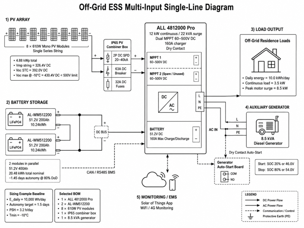
- Continuous load is 3.5kW; peak surge demand is 8.5kW.
- Inverter Selection: Select ALL 4812000 Pro (12kW Continuous / 22kVA Surge). The 12kW continuous rating covers the continuous load requirement, while the 22kVA surge capacity supports the motor startup demand.
Step 2: Battery Storage Sizing
Apply the battery capacity sizing formula:
E_bat_req = (10.0 kWh × 1.5 Days) ÷ (0.80 DoD × 0.93 Inverter Efficiency × 0.95 Temperature Factor)
E_bat_req = 15.0 ÷ 0.7068 = 21.22 kWh
- Module Selection: Select two (2) AL-WM512200 Wall-Mounted Battery Modules in parallel.
- Total Installed Battery Energy = 2 × 10.24 kWh = 20.48 kWh nominal capacity (400Ah total capacity at 51.2V). This provides approximately 1.45 days of off-grid autonomy at 80% DoD.
Step 3: PV Array Peak Power Sizing
Apply the PV peak capacity formula:
P_PV_peak = (10,000 Wh × 1.25 Oversizing Factor) ÷ (3.2 PSH × 0.88 System Efficiency)
P_PV_peak = 12,500 ÷ 2.816 = 4,438.9 Wp (4.44 kWp)
- Module Sizing: Select Haven Deer 610W Monocrystalline Modules.
- Number of modules required = 4,438.9W ÷ 610W = 7.27 modules → Round up to 8 modules.
- Total PV Array Capacity = 8 × 610W = 4,880Wp (4.88kWp).
Step 4: String Matching & V_oc Cold-Weather Check
Connect 8 PV modules in a single series string to MPPT Channel 1 of the ALL 4812000 Pro:
- V_mp_string = 8 × 40.8V = 326.4V DC (Within the optimal 60–500V DC MPPT operating range).
- V_oc_STC = 8 × 49.0V = 392.0V DC.
- Calculate V_oc_max at T_min = -10°C using the PV module temperature coefficient α_Voc = -0.28%/°C:
V_oc_max = 392.0 × [1 + (-0.28 ÷ 100) × (-10 – 25)]
V_oc_max = 392.0 × 1.098 = 430.4V DC
- Safety Verification: V_oc_max = 430.4V DC, which is below the 500V DC maximum input limit. PV string design is validated.
Step 5: DC Protection & Auxiliary Integration
- PV Combiner Box: Install an IP65 PV Combiner Box equipped with a 2P 20–40kA DC Surge Protection Device (SPD), 63A DC Circuit Breaker, and 32A DC Fuses between the PV array and inverter.
- Auto-Start Generator: Connect an 8.5kVA diesel generator to the shared AC input terminal. Connect the inverter Dry Contact relay to the generator auto-start controller. Configure trigger limits: Start at 20% SOC (or low-voltage threshold); Stop at 80% SOC (or charging target voltage).
7.3 Final Bill of Materials (BOM) — 10 kWh/Day Off-Grid Solar ESS Kit
| Component Type | Model Selection | Quantity | Primary Technical Specifications |
|---|---|---|---|
| Hybrid Inverter | ALL 4812000 Pro | 1 Unit | 12kW continuous / 22kVA surge, Dual MPPT, 160A charger, Dry Contact |
| Battery Storage | AL-WM512200 | 2 Modules | 51.2V 200Ah (20.48kWh total), Grade A LiFePO4, CAN/RS485 BMS |
| Solar PV Modules | Haven Deer 610W Mono | 8 Modules | 4.88kWp total array, Monocrystalline Grade A cells |
| PV Protection | IP65 Combiner Box | 1 Unit | 500V DC SPD (20–40kA), 63A Breaker, 32A DC Fuses |
| System Management | Solar of Things App | Integrated | Built-in WiFi / 4G remote monitoring and EMS energy management control |
8. Common System Sizing Mistakes & Field Mitigation Strategies
Field installation experience highlights recurring system sizing and commissioning errors that can reduce off-grid Solar ESS reliability and operational availability:
                              [Common Field Design Failures]
                                            │
           ┌────────────────────────────────┼────────────────────────────────┐
           ▼                                ▼                                ▼
 [PV Overvoltage Risk]    [Low-Temperature Charge Protection]    [Inverter Surge Trip]
(V_oc exceeds 500V DC)      (BMS blocks charging below 0°C)     (Motor startup surge ignored)
| Field Design Failure | Underlying Sizing Mistake | Field Impact on Site | Engineering Mitigation Strategy |
|---|---|---|---|
| MPPT Overvoltage Destruction | Sizing PV string V_oc using 25°C STC values without applying local T_min cold-weather correction. | Inverter MPPT input protection may fail during cold sunny mornings when PV string V_oc exceeds the 500V DC maximum input limit. | Always calculate V_oc_max at T_min and maintain a minimum safety margin below the 500V DC maximum input limit. |
| Winter Battery Charge Lockout | Installing LiFePO4 battery packs in unheated, uninsulated outdoor locations. | Integrated BMS triggers low-temperature charge cutoff below 0°C to reduce lithium plating risk during charging. | Install batteries inside insulated equipment rooms or specify thermal heating enclosures. |
| Inverter Overload Shutdown | Sizing inverter capacity strictly based on continuous running watts. | Inverter trips on overload whenever water pumps or compressor motors cycle on. | Size inverter continuous power and surge capability based on the maximum combined operating load and motor startup demand. |
| Premature Battery Depletion | Omitting inverter DC-to-AC conversion losses during battery Wh calculation. | Battery bank depletes faster than expected, causing reduced backup duration and unexpected load shedding. | Apply inverter conversion efficiency and battery round-trip efficiency factors when calculating required battery capacity. |
8.1 Pre-Commissioning Sizing Verification Checklist for Installers
Before energizing an off-grid Solar ESS kit, verify all installation parameters against this engineering checklist:
- Load Verification: Verify that total continuous AC loads do not exceed rated inverter wattage (6kW for ALL 486000 Pro; 12kW for ALL 4812000 Pro).
- Surge Verification: Confirm that peak motor starting surge power remains below peak surge rating (12kVA for 6kW model; 22kVA for 12kW model).
- Cold V_oc Verification: Measure PV string open-circuit voltage under installation conditions and confirm the calculated V_oc_max remains below the 500V DC maximum input limit.
- Polarity Check: Confirm correct DC voltage polarity on PV input terminals and battery cable connections before closing breakers.
- Communication Cable: Verify CAN or RS485 communication cable pinout between the Master Battery BMS communication port and the inverter communication interface.
- BMS Address Switches: Verify unique DIP switch address assignments on all parallel battery packs (Master = Address 1; Slave units = Address 2, 3, and subsequent addresses).
- Dry Contact Signal: Confirm dry contact relay signal wiring to the auxiliary generator auto-start board and verify SOC threshold settings in the EMS menu.
- Grounding Verification: Confirm the system grounding conductor is correctly connected between the PV combiner box, inverter chassis ground, and PV module mounting structure according to local electrical requirements.
9. Frequently Asked Questions (FAQ)
Q1: How do I calculate the battery capacity needed for my off-grid system?
Calculate required battery capacity by multiplying daily energy consumption (kWh/day) by required autonomy days, then dividing by DoD, inverter conversion efficiency, and temperature correction factor. A typical residential design uses 80% DoD, 0.93 inverter efficiency, and a temperature correction factor based on installation climate conditions.
Q2: Why is continuous inverter power distinct from surge power during sizing?
Resistive loads (lights and heaters) draw constant continuous power. Inductive loads (air conditioners, pumps, and compressors) require a short-duration startup surge that can reach approximately 3× to 5× their continuous running power during motor startup. The inverter continuous rating must satisfy normal operating loads, while the surge rating must handle startup demand without triggering overload protection.
Q3: What happens if the PV open-circuit voltage (V_oc) exceeds 500V DC?
Exceeding the inverter’s 500V DC maximum PV input limit can damage the MPPT input stage and may invalidate warranty coverage according to product terms. PV string configurations must be calculated using the lowest historical site temperature (T_min) to ensure cold-weather V_oc increase remains below the 500V DC maximum input limit.
Q4: How does a dual MPPT inverter benefit off-grid sizing?
Dual independent MPPT channels (available on the ALL 4812000 Pro) allow PV arrays with different orientations, such as East and West roof sections, or different string configurations to connect to the same inverter while maintaining independent maximum power tracking.
Q5: Can I expand battery capacity later if energy consumption increases?
Yes. Haven Deer modular 51.2V LiFePO4 batteries support parallel expansion with up to 6 units recommended. Additional identical battery modules connect through a shared DC busbar and master-slave CAN/RS485 communication to enable coordinated BMS operation.
Q6: How does auto-start Dry Contact logic work with backup generators?
The hybrid inverter EMS monitors battery SOC and voltage. When battery storage reaches a programmed low threshold, the inverter closes a passive Dry Contact relay that sends a start signal to the generator controller. Once the battery reaches the configured charging threshold, the relay opens and sends a generator shutdown signal.
Q7: What is the optimal Depth of Discharge (DoD) for residential LiFePO4 batteries?
Daily cycling at 80% DoD provides a balanced design point between usable energy and long-term battery service life, delivering ≥10,000 cycles to 80% EOL under standard operating conditions.
Q8: Why is dual AC output important for off-grid load management?
Dual AC output separates essential loads (Main Output) from non-essential loads (Smart Load). During grid outages or low battery SOC conditions, the EMS can disconnect the Smart Load output according to configured thresholds, preserving available battery energy for critical loads connected to the Main Output.
Q9: Do cold winter temperatures affect battery sizing?
Yes. Lithium Iron Phosphate batteries require charging temperature protection because charging below 0°C increases lithium plating risk. Integrated BMS controllers automatically disable charging when cell temperature reaches the low-temperature protection threshold. Batteries installed in cold climates should be placed inside insulated equipment rooms or fitted with thermal enclosures.
Q10: How many solar panels can be wired into a single string for a 48V hybrid inverter?
For standard 610W monocrystalline modules (V_oc ≈ 49.0V), a series string of 6 to 8 modules produces an STC V_oc range of approximately 294V to 392V DC. This configuration operates within the inverter’s 60–500V DC MPPT operating range while maintaining a cold-weather voltage margin below the 500V DC maximum input limit.
10. Request an Engineering Project Design Review
Designing a complete off-grid Solar Energy Storage System requires coordinated evaluation of electrical sizing, thermal conditions, installation environment, and system integration requirements. Haven Deer provides pre-engineered off-grid ESS kits and engineering support for solar installers, EPC contractors, and local distributors worldwide.
Need assistance verifying load profiles, PV string sizing, battery configuration, or single-line diagrams (SLD) for an upcoming off-grid ESS project?
Contact Haven Deer Engineering Support for Off-Grid ESS System Design Assistance