Quick Answer: Inverter frequency drift occurs when a generator governor fails to hold engine speed (RPM) during dynamic load shifts. This pushes output frequency outside the hybrid inverter’s AC acceptance range. Unstable frequency causes continuous relay chattering as the AC switch repeatedly cycles. Fix this by enabling generator mode (such as APL) to widen acceptance limits, properly sizing the genset for site loads plus battery charging, and programming EMS dry contact delays for engine warm-up.
1. The Physics of Generator Frequency Drift and Inverter AC Rejection
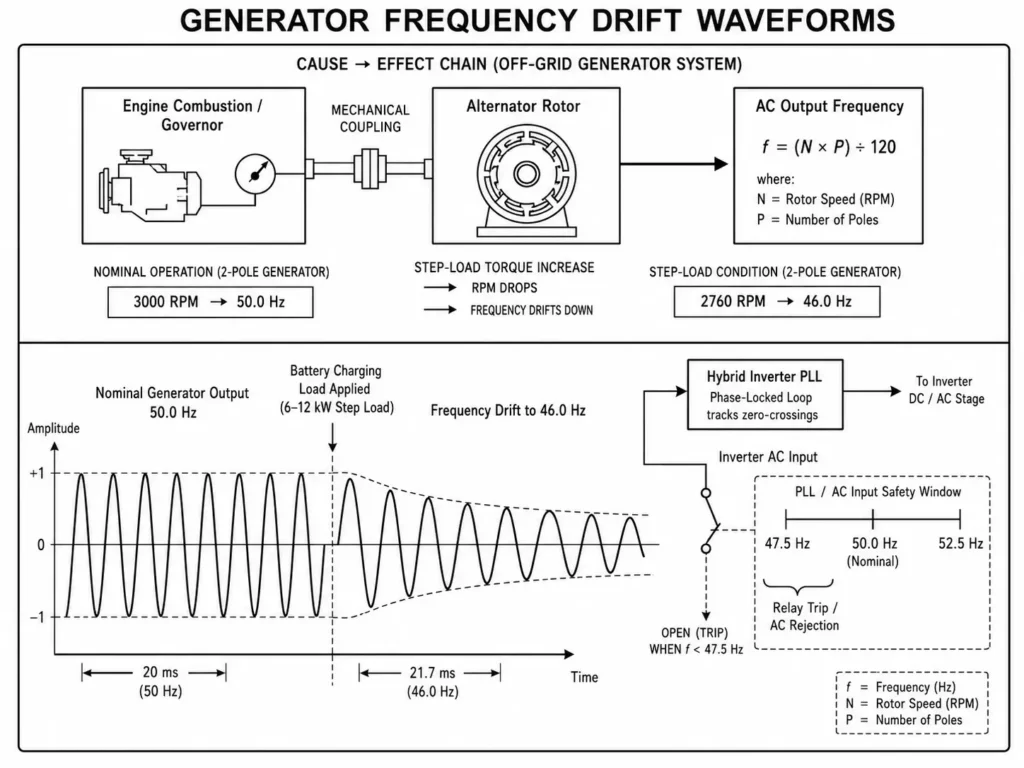
In off-grid systems, generator frequency is inherently less stable than utility grids because engine speed directly drives alternator frequency. Alternator speed directly dictates AC output frequency:
f = (N × P) ÷ 120
Where:
- f = Alternator AC Output Frequency (Hz)
- N = Engine Rotational Speed (RPM)
- P = Number of Alternator Magnetic Poles
A standard 2-pole generator must maintain 3000 RPM for 50 Hz output, or 3600 RPM for 60 Hz systems.
┌───────────────────┐      Mechanical Coupling      ┌───────────────────┐
│ Engine Combustion │ ────────────────────────────► │ Alternator Rotor  │
│   (RPM Control)   │                               │  (Field Windings) │
└─────────┬─────────┘                               └─────────┬─────────┘
          │                                                   │
          ▼                                                   ▼
  Engine Speed (N)                               Output Frequency (f)
  3000 RPM Nominal                                   50 Hz Nominal
When detecting AC input, a hybrid inverter’s Phase-Locked Loop (PLL) synchronizes with the generator waveform before closing the transfer relay. Closing the relay to charge batteries adds sudden mechanical torque to the rotor. If the governor lags, engine speed drops immediately.
1.1 Mechanical Governor Lag and Engine Speed Drops (N ↔ f)
Applying a sudden 6 kW or 12 kW step-load forces the mechanical governor—whether centrifugal or pneumatic—to sense the RPM drop and quickly open the throttle.
Mechanical inertia and fuel lag delay governor recovery. During this transient window, engine RPM drops sharply before recovering.
- Nominal State: 3000 RPM → f = (3000 × 2) ÷ 120 = 50.0 Hz
- Step-Load Drop: 2760 RPM → f = (2760 × 2) ÷ 120 = 46.0 Hz
An 8% frequency drop (50.0 Hz to 46.0 Hz) triggers inverter safety limits to protect downstream loads.
| Alternator Poles (P) | Nominal Speed (50 Hz) | Speed at 47.5 Hz (-5%) | Speed at 45.0 Hz (-10%) |
| 2-Pole Alternator | 3000 RPM | 2850 RPM | 2700 RPM |
| 4-Pole Alternator | 1500 RPM | 1425 RPM | 1350 RPM |
1.2 Inverter AC Phase-Locking (PLL) and Frequency Threshold Safety Limits
Digital signal processors (DSP) in hybrid inverters continuously track AC input by measuring voltage zero-crossings via PLL.
Compliance standards like IEC 62109-1 safety of power converters in photovoltaic systems mandate precise protection tripping whenever AC input conditions breach configured operational windows.
If frequency drifts faster than the PLL slew rate or exceeds threshold limits, the DSP trips the AC input relay.
Engineering Tip: Inspect mechanical speed controls before tweaking inverter software. Worn governors, dirty fuel filters, or sticky linkages magnify frequency swings during load steps.
2. Identifying Field Symptoms: Relay Chattering, Disconnect Loops, and EMS Alarms
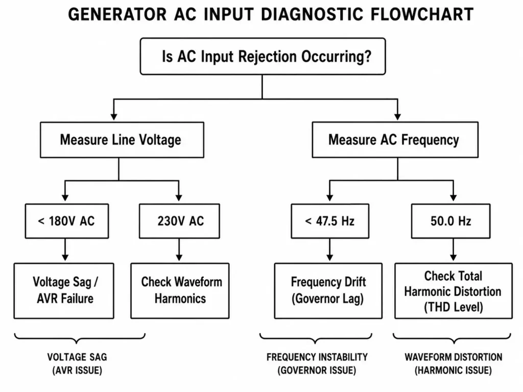
Troubleshooting off-grid generator compatibility requires isolating frequency instability, voltage sags, and harmonic distortion as separate root causes.
2.1 Diagnosing Frequency Hunting vs. Voltage Collapse
Frequency drift and voltage collapse look identical under heavy load, but stem from different controls and require different fixes.
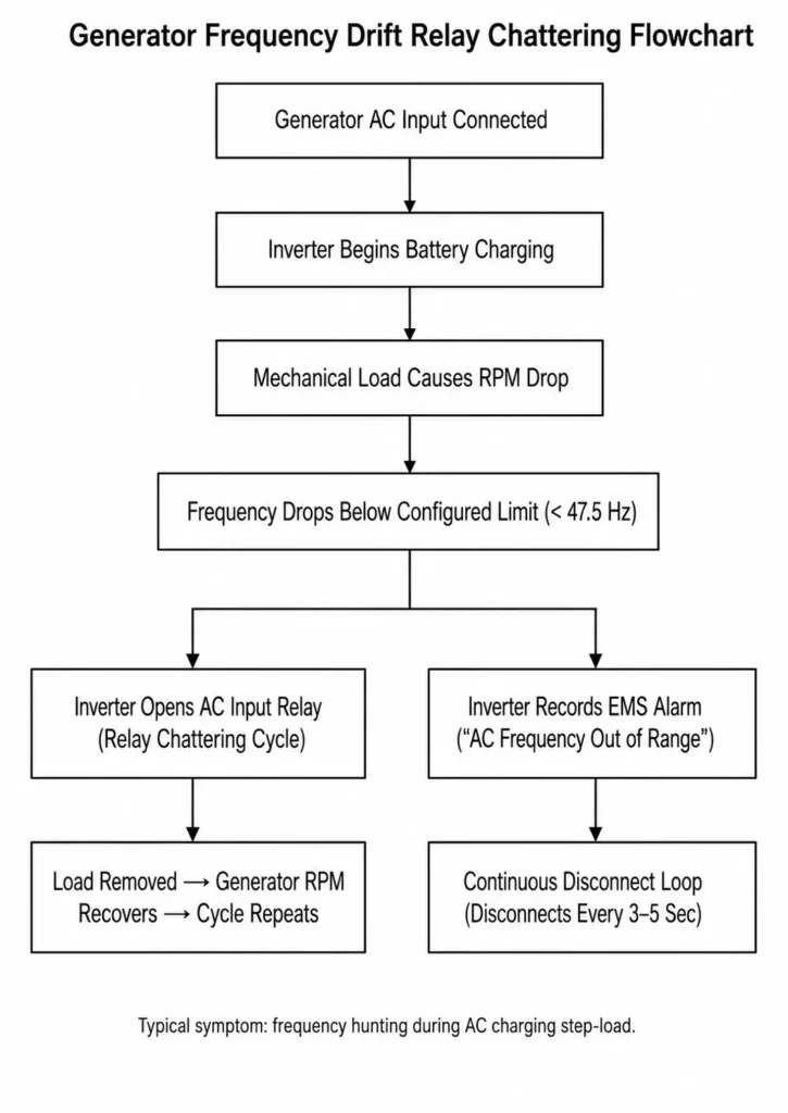
Frequency Hunting / Drift: Driven by governor lag, low engine headroom, or step-loads. Voltage holds steady, but dropping RPM pulls frequency below the inverter’s cutoff limit.
Voltage Collapse: Triggered by poor AVR response, weak excitation, or an undersized alternator. Engine RPM stays steady while voltage sags well below 230V AC.
2.2 The Mechanics of AC Transfer Relay Chattering
Relay chattering occurs when fluctuating AC input forces the internal transfer contactor to cycle rapidly.
- Qualification Phase: The inverter measures clean 230V AC / 50 Hz generator power for its qualification period.
- Relay Engagement: The transfer relay closes. The hybrid inverter activates its AC charging function and begins increasing charging current into the 51.2V LiFePO4 battery bank.
- Engine Deceleration: The sudden charging load reduces engine RPM temporarily, causing generator frequency to decrease.
- Safety Trip: The inverter DSP detects frequency outside the configured protection range and opens the AC input relay.
- Recovery: With the charging load removed, the generator restores engine speed and frequency.
- Loop Reset: The inverter detects restored AC conditions and restarts the qualification timer, repeating the connection and disconnection cycle until the generator stability issue is corrected.
| Diagnostic Symptom | Measured Parameter | Primary Root Cause | Corrective Action |
| Relay Chattering (3–5s loop) | Voltage: 230V AC Frequency: 44–46 Hz | Engine RPM drop during battery charging step-load | Configure generator-compatible frequency settings; reduce AC charging current |
| Instant Disconnect on Connection | Voltage: 160–180V AC Frequency: 50 Hz | AVR response limitation or insufficient generator capacity | Improve generator voltage regulation or reduce battery charging power |
| Inverter Ignores AC Entirely | Voltage: 230V AC Frequency: 50 Hz | Excessive THD or unstable waveform quality | Verify generator waveform quality and use a compatible low-distortion generator |
Common Mistake: Replacing the inverter during relay chattering. Chattering is usually a protective response to poor AC frequency, not a hardware failure.
Modern EMS platforms log these AC faults directly, simplifying field diagnostics when reviewing app error codes.
3. Configuring Inverter AC Input Windows: UPS Mode vs. APL / Generator Mode
Prevent AC input rejection on unstable generators by shifting the inverter’s input settings from narrow grid thresholds to wider generator acceptance ranges.
3.1 Standard Appliance Mode (APL) Frequency Parameters (40 Hz – 70 Hz)
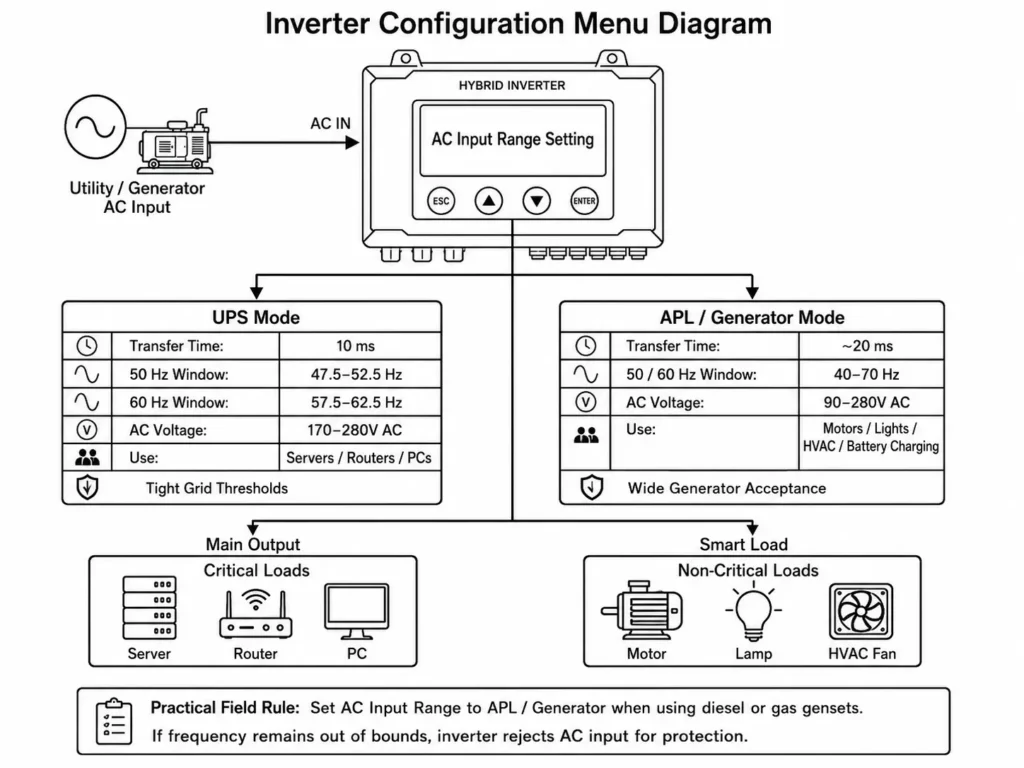
Hybrid inverters feature selectable operational modes to adapt DSP voltage and frequency acceptance windows:
- UPS Mode: Built for clean utility grids. It enforces tight frequency windows (47.5–52.5 Hz for 50 Hz systems) to ensure fast 10 ms transfer times for sensitive electronics.
- APL Mode (Generator Mode): Expands input thresholds (40–70 Hz frequency; 90–280V AC voltage) to handle engine frequency drift, extending transfer time to ~20 ms.
| Parameter | UPS Mode (Default Grid) | APL / Generator Mode |
| Transfer Time | 10 ms (UPS Class) | 20 ms (Appliance Class) |
| Nominal 50 Hz Frequency Window | 47.5 Hz – 52.5 Hz (±2.5 Hz) | 40.0 Hz – 70.0 Hz |
| Nominal 60 Hz Frequency Window | 57.5 Hz – 62.5 Hz (±2.5 Hz) | 40.0 Hz – 70.0 Hz |
| AC Input Voltage Window | 170V AC – 280V AC | 90V AC – 280V AC |
| Primary Target Load | Servers, Routers, PCs | Motors, Lights, HVAC, LFP Battery Chargers |
APL mode lets the inverter ride through temporary RPM drops while the governor stabilizes under heavy charging loads.
3.2 Impact of Wide AC Acceptance on Sensitive Downstream Loads
Wider tolerance prevents nuisance tripping, but engineers must evaluate downstream load sensitivity:
- Dual AC Output Architecture: Haven Deer hybrid inverters, including the ALL 486000 Pro (6 kW single MPPT) and ALL 4812000 Pro (12 kW dual MPPT), feature dual AC outputs to isolate essential loads from controllable secondary loads.
- Main Output vs. Smart Load: Connect critical loads to the Main Output and route non-essential equipment to the Smart Load terminal for dynamic power management via Dual AC Output Engineering: Main vs. Smart Load.
If frequency remains out of bounds even under APL mode, internal protection logic trips the AC source to protect system components.
Practical Field Rule: Always set the AC Input Range to “APL” or “Generator” mode when running conventional diesel or gas gensets.
4. Generator Sizing and Governor Tuning for Energy Storage Systems
Widening frequency windows is only a partial fix. Applying exact rules for sizing diesel/gas generators for off-grid battery recharging ensures the engine absorbs dynamic step-loads without tripping.
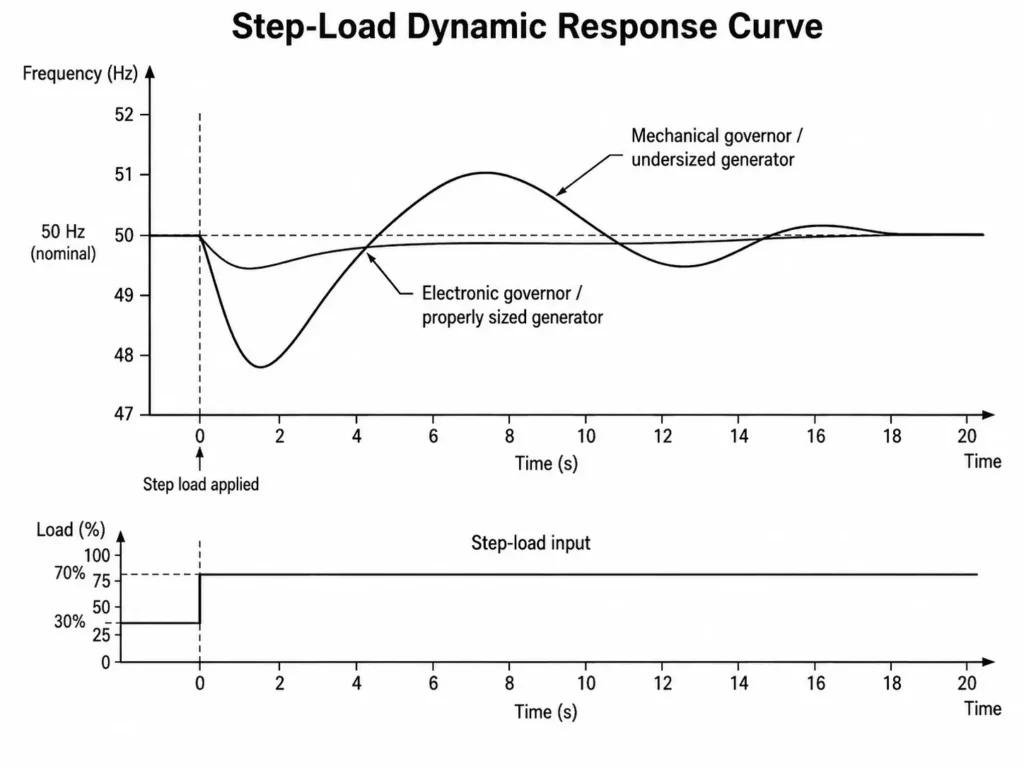
4.1 The 1.5× – 2.0× Inverter Capacity Sizing Rule
Sizing gensets 1:1 with hybrid inverters (e.g., a 6 kW generator on a 6 kW inverter) is a common field mistake.
When operating under hybrid energy management for PV + generator dual charging, the generator must simultaneously power site AC loads and supplement solar output to charge a depleted battery bank.
Engines cannot take instant block loading without dropping RPM. Continuous generator rating must exceed total calculated load.
Generator Sizing Formula
Sgen = [(PAC_Load + PDC_Charging) ÷ (ηinverter × PFgen)] × SF
Where:
- Sgen = Minimum Required Generator Capacity (kVA)
- PAC_Load = Continuous AC House / Facility Load (kW)
- PDC_Charging = Maximum battery charging power delivered from the inverter to the DC battery side (kW)
- ηinverter = Inverter Efficiency (typically 0.90 to 0.93)
- PFgen = Generator Power Factor (typically 0.8 for three-phase / 1.0 for quality single-phase)
- SF = Safety & Step-Load Factor (1.5 to 2.0)
Worked Engineering Sizing Example
Take a rural site with a Haven Deer ALL 4812000 Pro (12 kW) and two MB512300 batteries (51.2V 300Ah, 30.0 kWh total):
- Continuous AC House Load: 4.0 kW
- Configured Inverter AC Charging Current: 100A at 51.2V DC = 5.12 kW battery charging power
- Total Active Power Required: 4.0 kW + 5.12 kW = 9.12 kW
- Inverter Efficiency Loss Adjustment: 9.12 kW ÷ 0.93 = 9.81 kW input from generator
- Power Factor Adjustment (PF = 0.8): 9.81 kW ÷ 0.8 = 12.26 kVA base load
Applying the minimum recommended Step-Load Safety Factor of 1.5×:
Sgen = 12.26 kVA × 1.5 = 18.39 kVA
In this scenario, specify a 20 kVA to 22 kVA generator. This absorbs the 5.12 kW charging step-load, lowers governor stress, and prevents frequency sags.
| Inverter Model | Max Charging Power | House Load Assumption | Calculated Base kVA | Recommended Generator Size |
| 6 kW Hybrid (ALL 486000 Pro) | 5.12 kW charging power | 2.0 kW | 8.9 kVA | 13.5 kVA – 15 kVA |
| 12 kW Hybrid (ALL 4812000 Pro) | 8.19 kW charging power | 4.0 kW | 15.3 kVA | 22 kVA – 25 kVA |
4.2 Electronic AVR vs. Mechanical Governors in Off-Grid Microgrids
When specifying generators for EPC microgrid projects, governor response classes defined under the ISO 8528-5 performance standard for generating sets directly dictate dynamic frequency stability.
- ISO 8528-5 Class G1 / G2 (Mechanical Governors): Common mechanical units exhibit high speed droop under load changes. Significant RPM sags during battery charging require wider inverter frequency settings or reduced charge current.
- ISO 8528-5 Class G3 / G4 (Electronic Governors & Inverter-Generators): Electronic speed controls react instantly to step-loads, holding tight frequency limits. These are ideal for high-current LFP charging.
Common Mistake: Maxing out AC charging current on small generators. Throttling charge current from 100A to 40A in the EMS reduces step-load shock and stabilizes frequency.
5. Automated Dry Contact Control and Load Delay Synchronization
Automated dry contact logic prevents start-up frequency instability by decoupling engine cranking from battery charging.
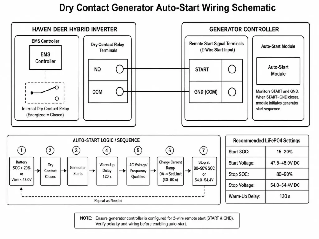
5.1 Setting SOC and Voltage Thresholds for Auto-Start Logic
Instead of manual starts or continuous idling, the inverter EMS tracks battery SOC or voltage and triggers the generator using automated generator integration via passive dry contacts.
Prevent short-cycling and optimize runtimes by correctly setting dry contact trigger thresholds (SOC % vs voltage) based on battery chemistry:
| System Parameter | Recommended Setting (LiFePO4) | Engineering Rationale |
| Generator Start SOC % | 15% – 20% SOC | Prevents deep discharge while maintaining reserve capacity |
| Generator Start Voltage | 47.5V – 48.0V DC | Backup trigger when reliable SOC information is unavailable |
| Generator Stop SOC % | 80% – 90% SOC | Avoids inefficient generator operation during late charging stages |
| Generator Stop Voltage | 54.0V – 54.4V DC | Voltage-based stop reference during charging |
| Warm-Up Delay Timer | 120 Seconds | Allows engine temperature and RPM to stabilize before loading |
5.2 Implementing Generator Warm-Up Delays and Step-Load Charging
Cold engines respond poorly to immediate loads. Hybrid inverters use timed multi-stage sequences to let gensets stabilize before ramping charge power:
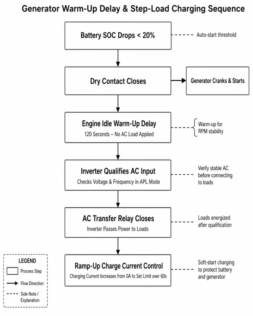
- Start Signal: The inverter dry contact closes when reaching the configured battery threshold (e.g., 20% SOC).
- Engine Warm-Up Delay: The genset runs unloaded for a preset window (e.g., 120 seconds). This lets oil pressure, engine temp, and RPM normalize before taking on load.
- Qualification & Soft Transfer: The inverter verifies AC voltage and frequency. Once qualified, the transfer relay closes.
- Current Ramp-Up (Soft Start): The EMS ramps AC charge current from 0A to max over 30–60 seconds rather than step-loading the engine. This soft-start prevents torque spikes and holds frequency steady.
Engineering Tip: Extend warm-up delays in cold climates. Slamming full charging loads onto a freezing engine triggers instant frequency drops and stall trips.
6. Field Checklist: Step-by-Step Protocol to Eliminate Frequency Instability
Use this commissioning protocol alongside the comprehensive commissioning checklist for installers during first-time setup to eliminate frequency drift and prevent relay chattering:
- Step 1: Inspect Generator Hardware. Check air filters, fuel quality, and governor linkages. Confirm the generator hits rated no-load speed (3000 RPM for 50 Hz / 3600 RPM for 60 Hz).
- Step 2: Set AC Input Range to APL / Generator. Switch AC Input Range from UPS to APL (or Generator) mode via the LCD or app. This widens acceptance limits to 40–70 Hz.
- Step 3: Cap AC Charging Current. Derate max AC charging current in the EMS to match generator continuous kVA. Keep total load (house + charging) under 80% generator capacity.
- Step 4: Wire Dry Contact Auto-Start. Run a 2-wire signal cable from inverter dry contacts (NO/COM) to the generator controller. Program triggers (e.g., 20% SOC / 48.0V start; 85% SOC / 54.0V stop).
- Step 5: Enable Warm-Up Delay & Soft-Start. Set a 120-second engine warm-up delay in the EMS. Enable charge soft-start to ramp charging power over 30–60 seconds.
- Step 6: Validate Under Load. Run a manual start test and log frequency using a True-RMS meter across three stages:
- Unloaded Warm-Up Phase: Verify frequency stability before AC transfer.
- AC Transfer Phase: Confirm frequency stays within inverter transient thresholds during relay closure.
- Full Charging Load Phase: Ensure steady-state frequency remains stable under full configured charging power.
7. Frequently Asked Questions
Why does my hybrid inverter disconnect every time the generator starts?
Genset speed fluctuates during startup before settling. In standard UPS mode, tight frequency limits (47.5–52.5 Hz) reject these momentary swings and trip the AC relay. Switching to APL / Generator mode widens the input window to 40–70 Hz, letting the inverter ride through startup transients.
What is inverter relay chattering?
Relay chattering occurs when fluctuating AC forces the internal transfer contactor to cycle rapidly. The inverter connects, applies charging load, senses an RPM sag, trips on low frequency, and then reconnects once RPM recovers—creating an endless loop.
What is the difference between UPS mode and APL mode on a solar inverter?
UPS Mode: Enforces fast 10 ms transfer times with tight frequency limits (47.5–52.5 Hz) for sensitive IT equipment on stable grid power.
APL Mode (Generator Mode): Relaxes transfer times to ~20 ms and expands acceptance limits (40–70 Hz, 90–280V AC) to tolerate typical generator frequency drift.
Will running my inverter in APL mode damage my home appliances?
No. Standard loads like motors, pumps, lights, and power supplies run reliably in APL mode. Route sensitive electronics to the inverter’s dedicated Main AC output to isolate them from raw generator power.
How big should my generator be to charge a 48V LFP battery bank?
Size generator continuous capacity 1.5× to 2.0× higher than the combined house load and maximum battery charge power. For a 6 kW hybrid inverter charging at 100A, specify a 13.5 kVA to 15 kVA genset to handle charge step-loads without stalling.
Can I adjust maximum AC charging current to stop generator frequency drop?
Yes. Throttling the AC charge current in the EMS directly reduces mechanical torque demand on the engine. Dropping charge current from 100A to 40A or 50A softens the step-load, stabilizing engine RPM and output frequency.
How does dry contact auto-start prevent generator stall?
Dry contact auto-start lets the inverter command engine start timing. Programming a warm-up delay keeps the generator unloaded until oil pressure and engine RPM stabilize, preventing instant load stalling.
Why does my generator voltage stay stable at 230V, but the inverter still rejects it?
The AVR holds output voltage steady at 230V, but cannot control engine RPM. Dropping engine RPM pulls output frequency below the inverter’s cutoff limit even while voltage stays flat.
Can I connect a portable gasoline generator to a Haven Deer hybrid inverter?
Yes. Wire portable gas gensets to the AC input terminal, set the inverter to APL mode, and derate the EMS battery charging current to match the generator’s continuous running watts.
Does total harmonic distortion (THD) cause inverter disconnects?
Yes. Cheap generators produce high voltage THD, distorting the waveform. This throws off zero-crossing detection, preventing the inverter’s Phase-Locked Loop (PLL) from locking synchronization—even if voltage and frequency look normal.
What parameter controls engine warm-up time in Haven Deer inverters?
Set the Dry Contact Generator Warm-Up Delay parameter in the EMS menu. This controls the delay between start signaling and transfer relay closure.
Should I ground the generator frame to the inverter AC earth terminal?
Yes. Bond the generator frame, inverter enclosure, and main grounding electrode in full compliance with NEC Article 250 equipment grounding requirements. Proper grounding ensures fault current paths clear overcurrent devices during AC ground faults.
8. Designing a High-Reliability Off-Grid Microgrid
Mismatched inverter settings, undersized generators, and lagging governors compromise off-grid system reliability.
Haven Deer helps EPC contractors and distributors optimize microgrid designs—from single-line diagram reviews to mastering how integrated EMS coordinates PV, battery, grid, and generator power sources under dynamic site loads.