Quick Answer:An off-grid solar ESS for remote outposts and island microgrids integrates PV generation, a multi-input hybrid inverter Energy Hub, and Grade A LiFePO4 batteries. Automated dry-contact generator controls ensure reliable AC power off-grid.
1. Core Technical Challenges of Isolated Island & Remote Outpost Grids
Deploying electrical infrastructure on remote islands, marine stations, and mountain outposts differs fundamentally from standard grid-tied solar design. Without utility support, generation, storage, and automated backup controls must operate autonomously to maintain critical loads.
1.1 Fuel Logistics, Grid Absence, and Harsh Environmental Factors
Remote facilities historically relied on continuous diesel generation. However, running diesel generators as primary power introduces major operational vulnerabilities:
- High Levelized Cost of Energy (LCOE): Maritime transport, helicopter drops, and rough-terrain fuel transport drive up operational costs. Continuous generator operation quickly becomes economically unsustainable.
- Supply Chain Fragility: Severe weather, sea ice, or monsoon seasons block fuel deliveries for months. Prolonged supply disruption risks total blackout.
- Extreme Environmental Exposure: Salt mist, high humidity, ambient heat spikes, and sub-zero temperatures accelerate equipment corrosion. Harsh climates shorten component lifespan.
- Continuous Mechanical Operation: Running diesel gensets continuously causes severe engine wet-stacking at low loads. Unplanned maintenance spikes significantly off-grid.
1.2 Essential Load Prioritization vs. Unpredictable Irradiance
Solar irradiance on islands and high-altitude outposts fluctuates rapidly. Fog, sudden cloud cover, or multi-day storms cause sharp generation drops. Aligning system logic with NREL microgrid design guidelines, off-grid power systems must coordinate storage, PV, and loads dynamically without utility fallback.
Maintaining power continuity requires splitting site loads into Essential Loads (satellite comms, refrigeration, desalination, medical gear, navigation lights) and Non-Essential/Smart Loads (HVAC, water heating, general power). During extended low-irradiance windows, the BMS and EMS shed non-essential circuits to protect core operations.
| Parameter | Utility Grid Power | Isolated Island / Remote Outpost Microgrid |
| Grid Fallback Availability | Continuous utility supply | No external grid backup |
| Primary Power Source | Centralized grid generation | Solar PV + LiFePO4 Battery Storage |
| Backup Power Source | Optional standby generator | Automated Dry-Contact Generator Integration |
| System Transfer Requirement | Standard switching acceptable | 10ms UPS-level transfer for critical loads |
| Environmental Protection | Standard indoor installation | IP22 indoor equipment / IP65 outdoor PV protection |
| Maintenance Accessibility | Local service availability | Limited access requiring high system autonomy |
2. Multi-Input Energy Hub Architecture & Control Hierarchy
Off-grid microgrids rely on an Energy Hub to route multi-source power and manage bidirectional conversion. Integrated off-grid systems unify PV generation, battery storage, inverter controls, and generator backup into a single control architecture. Centralized control maintains voltage stability.
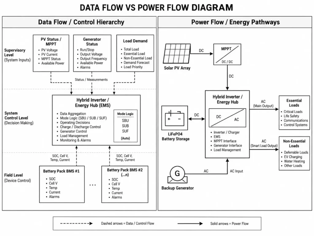
2.1 Coordinating Solar PV, Battery Storage, and Diesel Generators
The central Energy Hub—integrated within a hybrid inverter—manages four primary power pathways:
- Photovoltaic Generation (DC Input): Tracks array maximum power points (MPPT) to power AC loads and charge batteries directly.
- Bidirectional Battery Energy Storage (DC Interface): Stores excess solar yield and discharges during nighttime or low-irradiance windows.
- Auxiliary AC Input (Generator): Accepts generator AC power to carry site loads and recharge batteries during extended solar deficits.
- Dual Output AC Distribution (Load Interface): Supplies pure sine wave AC via independent Main and Smart Load outputs, separating essential loads from shed-able circuits.
The Haven Deer ALL 4812000 Pro hybrid solar inverter functions as a centralized Energy Hub for off-grid applications. Powered by an integrated EMS that coordinates PV, battery, grid, and generator controls, it manages total site energy dispatch. Dual MPPT trackers accept up to 15,000W total PV input across a 60–500V DC operating window.
2.2 Layered BMS and EMS System Dispatch Logic
System operation relies on a two-level control hierarchy that separates battery hardware protection from system-level energy management:
- Battery Management System (BMS): Operating inside each battery pack, the BMS monitors cell voltages, temperatures, charge/discharge currents, and SoC. It executes cell balancing alongside overvoltage, over-discharge, overcurrent, and thermal cutoffs. Hardware protection operates independently of network firmware.
- Energy Management System (EMS): Embedded within inverter control firmware, the EMS directs system dispatch logic. It analyzes PV input, load demand, battery SoC, and generator availability to set active power flow paths.
| Operating Strategy | Power Flow Priority | Operational Purpose in Island Microgrids |
| SBU Mode (Solar – Battery – Utility/Gen) | 1. Solar PV 2. LiFePO4 Battery 3. Generator | Primary Off-Grid Mode: Solar PV powers site loads first, storing excess energy in the battery bank. The battery carries night loads. The generator starts automatically when battery SoC drops to the low cutoff limit. |
| SUB Mode (Solar – Utility/Gen – Battery) | 1. Solar PV 2. Generator 3. LiFePO4 Battery | Battery Reserve Protection Mode: Solar PV powers loads first. If solar output drops, the generator engages before battery discharge to preserve battery capacity for critical utility or weather outages. |
| SUF Mode (Custom Priority) | Configurable via EMS | Specialized Control: Custom dispatch logic configured for specialized load profiles, tariff structures, or harsh seasonal operating schedules. |
3. LiFePO₄ Battery Storage Engineering for Harsh Off-Grid Operating Environments
Battery selection dictates microgrid lifespan, maintenance cycles, and uptime. Compared to lead-acid, Grade A LiFePO4 chemistry delivers deeper DoD, longer cycle life, and minimal maintenance. High DoD maximizes usable battery capacity off-grid.
3.1 Grade A Prismatic Cell Chemistry and Thermal Stability
Lithium Iron Phosphate (LiFePO4) remains the industry standard for stationary BESS, certified under IEC 62619 safety standards for industrial lithium batteries due to its intrinsic thermal and chemical stability. Unlike NMC cells, LiFePO4 chemistry resists thermal runaway under high temperatures and electrical abuse. Superior thermal stability prevents catastrophic failures.
Connecting Grade A prismatic aluminum-shell cells in a 16S configuration (51.2V DC nominal) delivers core engineering advantages:
- Extended Cycle Life: Grade A LiFePO4 cells deliver ≥6,000 cycles at 90% DoD and ≥10,000 cycles at 80% DoD (tested at 25°C).
- High Round-Trip Efficiency (RTE): Minimal internal resistance reduces round-trip conversion losses during daily charge-discharge cycling.
- Low Self-Discharge: Stable chemistry preserves stored energy during prolonged standby without significant capacity fade.
3.2 Floor-Standing Mobile Cabinet Batteries (15kWh / 18kWh) for Equipment Rooms
Mounting heavy battery banks on walls in remote shelters or retrofitted container outposts risks structural failure. Weak wall framing often requires expensive structural reinforcements before mounting high-capacity modules.
To streamline site deployment, Haven Deer provides heavy-duty floor-standing cabinet batteries: the MB512300 (51.2V 300Ah / 15.0kWh) and MB512346 (51.2V 346Ah / 18.0kWh).
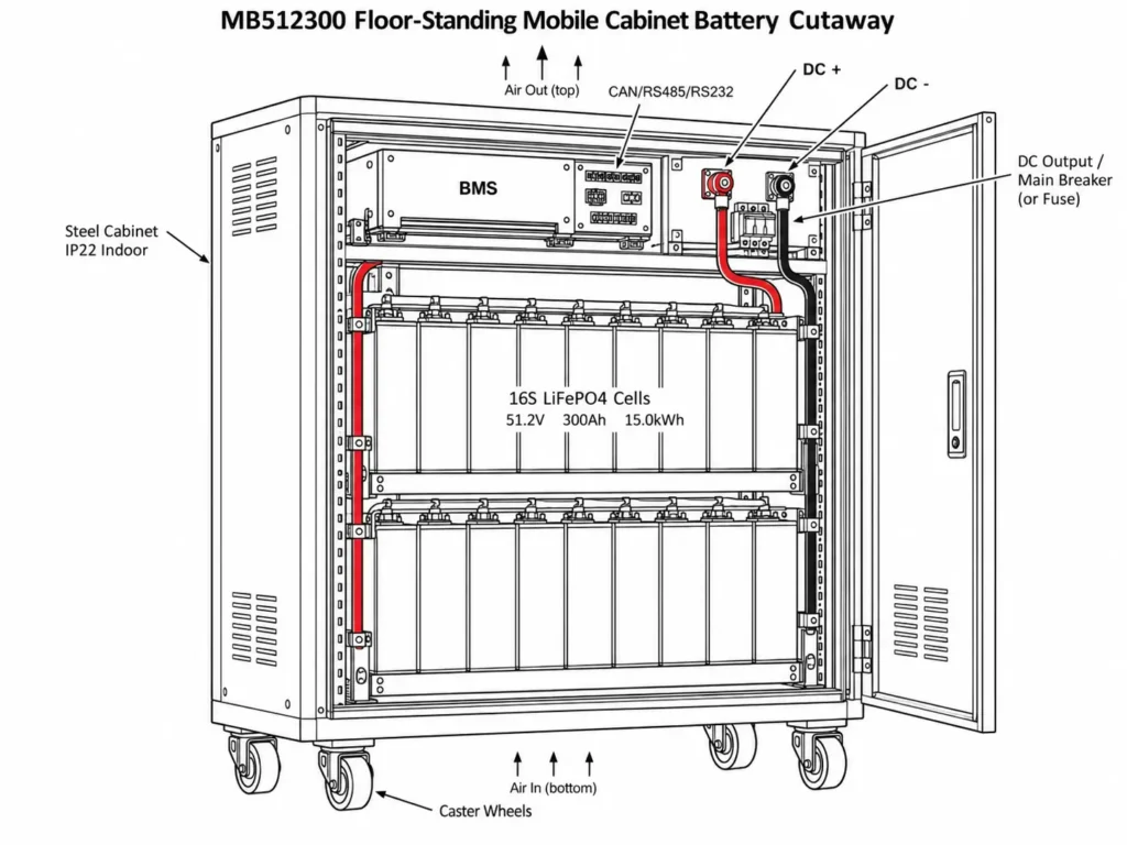
These cabinets house Grade A prismatic cells inside heavy-duty steel enclosures equipped with caster wheels and IP22 ingress protection. Sitting directly on equipment room floors, they simplify installation and enable closed-loop CAN/RS485/RS232 comms with the hybrid inverter BMS port.
| Technical Specification | Grade A LiFePO₄ Cabinet (MB512300) | Traditional Lead-Acid (AGM / GEL) |
| Usable Capacity (DoD) | 80%–90% Usable | Approximately 50% Usable |
| Cycle Lifespan (25°C) | ≥6,000 to 10,000 Cycles | 500 to 1,500 Cycles |
| Regular Maintenance | Low maintenance requirements | Regular inspection and maintenance required |
| Footprint / Weight Ratio | Compact / 129kg per 15kWh | Heavy and larger installation footprint |
| Battery Communication | Closed-loop CAN / RS485 / RS232 | Open-loop voltage estimation only |
| Charge Operating Temperature | 0°C to 50°C (55°C cabinet limit) | Limited performance at low temperatures |
| Discharge Operating Temperature | -15°C to 50°C (-20°C cabinet limit) | Performance decreases under cold conditions |
Common Engineering Mistake: Installing IP21 or IP22 indoor battery enclosures outdoors or in unprotected high-humidity environments. Always house indoor batteries in dry, ventilated equipment rooms. Protecting BMS electronics from salt mist prevents premature board failure.
4. Passive Dry Contact Generator Integration & Auto-Start Logic
Solar PV and batteries carry daily site loads, but multi-day solar deficits require automated genset backup. Automatic generator controls eliminate manual intervention at unmanned sites.
4.1 Setting SOC% vs. Battery Voltage Trigger Thresholds
The hybrid inverter executes automated generator integration via a built-in passive dry contact to manage standby genset auto-start cycles. This dry contact provides a voltage-free signal to two-wire remote-start terminals on standby gensets.
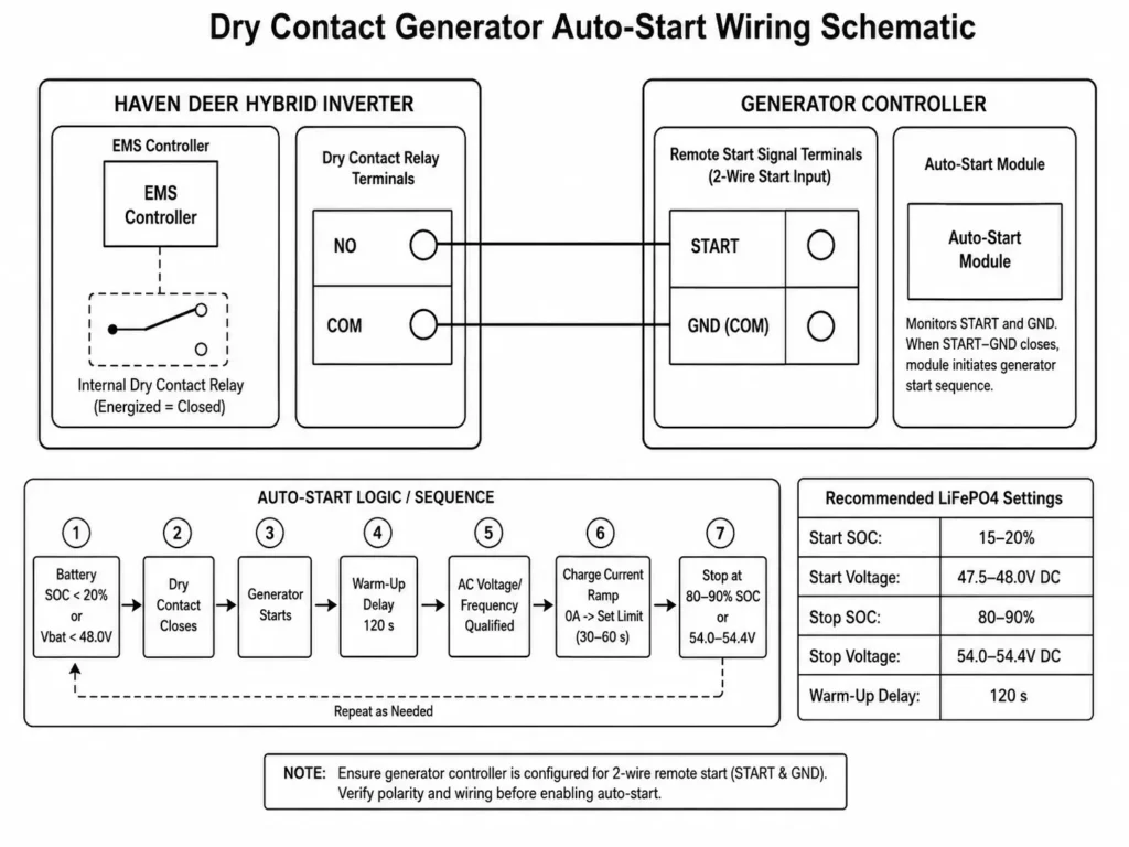
Engineers program EMS auto-start logic using closed-loop Battery State of Charge (SoC%) or DC voltage setpoints:
- Generator Start Trigger (Low Battery): When SoC drops to the low setpoint (typically 20%), the dry contact closes to signal generator startup.
- Generator Stop Trigger (Battery Recovered): Once generator AC power recharges the battery to the high threshold (typically 95%), the relay opens to initiate generator cool-down.
| Operational State | Trigger Metric | Threshold Parameter | Dry Contact Relay Action | System Response |
| Normal Operation | Battery SOC | >20% | OPEN | Solar PV and battery storage supply loads. Generator remains offline. |
| Low Battery Condition | Battery SOC | ≤20% | CLOSED | Dry contact sends generator remote-start signal. |
| Auxiliary Charging | Inverter AC Input | Active AC Input | CLOSED | Generator supplies AC power; inverter charges battery storage. |
| Battery Recovery Complete | Battery SOC | ≥95% | OPEN | Generator receives stop signal and completes shutdown sequence. |
4.2 Shared AC Input Routing and Automated Power Source Transfer
Haven Deer hybrid inverters feature a shared AC input bus for utility or generator power. Never feed grid and generator power simultaneously into a single AC port.
When the standby generator starts and stabilizes, the inverter executes an automated source transfer:
- UPS-Grade Transfer Speed: The internal transfer switch connects generator AC to site loads within 10ms for sensitive IT hardware or 20ms for general appliances.
- Voltage and Frequency Qualification: The inverter qualifies generator AC voltage and frequency (50Hz/60Hz) before closing input relays, protecting loads from dirty power.
5. Environmental Protection, IP Ratings, and Safeguards for Island Sites
Coastal and marine environments subject ESS hardware to salt mist, high humidity, and extreme heat. Matching IP ratings to zones ensures hardware uptime.
5.1 Enclosure IP Ratings (IP21/IP22 vs. Outdoor IP65 PV Combiner Box)
A complete off-grid solar ESS kit balances enclosure IP ratings against thermal management and service access requirements:
- IP21 / IP22 Indoor Units (Hybrid Inverters & Battery Cabinets): Hybrid inverters like the ALL 4812000 Pro (IP21) and MB512300 cabinet batteries (IP22) require climate-controlled indoor mounting. Always house indoor gear in ventilated shelters to block direct rain and salt spray.
- IP65 Outdoor Units (PV Combiner Boxes): Array string wiring routes directly into IP65-rated combiner boxes. Understanding why off-grid solar kits require IP65 PV combiner boxes comes down to ingress protection: dust-tight seals and water-jet resistance shield outdoor DC breakers, fuses, and SPDs from driving rain and severe weather.
| Hardware Component | IP Enclosure Rating | Installation Environment | Core Environmental Safeguards |
| Hybrid Solar Inverter | IP21 | Protected indoor equipment room | Ventilation, conformal-coated circuit boards |
| Mobile Cabinet Battery | IP22 | Protected indoor equipment room | Steel enclosure, drip-water protection |
| PV Combiner Box | IP65 | Outdoor installation near PV array | DC SPD (20–40kA), 63A breaker, 32A fuse |
| Mono Solar Panels | IP68 (Junction Box) | Roof-mounted / Ground array | Aluminum frame, tempered glass, IP68 connectors |
5.2 Mitigating Marine Humidity, Salt Mist, and Thermal Ambient Spikes
Airborne salt spray rapidly corrodes exposed copper terminals, busbars, and internal PCB traces. To survive severe coastal environments evaluated under ISO 9227 salt spray corrosion testing standards, installers must execute the following field protection steps:
- Conformal Coating: Ensure inverter control boards and BMS PCBs feature acrylic or silicone conformal coatings. Coating PCBs prevents airborne salt bridging and moisture short-circuits.
- Dielectric Protection: Coat exposed battery terminals, busbars, and high-current DC bolting points with dielectric grease or joint compound during assembly.
- Sealed Cable Glands: Torque IP-rated compression cable glands on outdoor combiner box knockouts and wall conduit penetrations. Sealed glands stop conduit moisture migration.
6. Practical Sizing & Single-Line Design for a 15–30kWh Remote Outpost
Designing isolated microgrids requires a step-by-step engineering guide to sizing off-grid ESS kits, ensuring precise calculations for battery autonomy margins, daily PV array yield, and cold-weather string Voc safety limits.
6.1 Load Calculation, Battery Autonomy Sizing, and PV Array String Design
Step 1: Gross Battery Storage Capacity Sizing
Calculate required gross battery capacity accounting for depth of discharge (DoD) and inverter conversion efficiency:
Cgross = (Eload × Dautonomy) ÷ (DoD × ηinverter)
Where:
- Eload = Daily energy demand (20 kWh/day)
- Dautonomy = Required autonomy period (2 days)
- DoD = Recommended battery depth of discharge (0.80 for 80% DoD)
- ηinverter = Battery-to-AC conversion efficiency (0.93)
Cgross = (20 kWh × 2) ÷ (0.80 × 0.93) Cgross = 40 ÷ 0.744 = 53.76 kWh
- Sizing Recommendation: Deploy 3 × Haven Deer MB512346 Floor-Standing Cabinet Batteries (18.0 kWh nominal capacity each × 3 = 54.0 kWh total storage capacity) in parallel. Deploying 54.0kWh nominal capacity satisfies the 53.76kWh threshold.
Step 2: Photovoltaic Array Sizing
Size the PV array for daily load delivery and battery recovery under an average solar resource of 4.5 Peak Sun Hours (PSH/day):
Ppv = (Eload + Erecharge) ÷ (PSH × ηsystem)
Assuming a total daily generation target of 30 kWh (20 kWh daily load + 10 kWh battery recharge) and a combined system derate factor of 0.80:
Ppv = 30 kWh ÷ (4.5 h × 0.80) Ppv = 30 ÷ 3.6 = 8.33 kWp
- Array Specification: Deploy 14 × 610W monocrystalline PV modules (14 × 610W = 8,540W or 8.54kWp total array capacity).
Step 3: String Configuration & Cold-Weather Voc Safety Check
When connecting PV modules to the Haven Deer ALL 4812000 Pro (12kW Dual MPPT) hybrid inverter, split the array equally across two independent MPPT channels (7 modules per string, 1 string per MPPT).
- Module Open Circuit Voltage at STC (Voc,STC) = 49.0V DC
- Voltage Temperature Coefficient (αVoc) = -0.27%/°C
- Lowest Expected Ambient Temperature (Tmin) = -10°C
Calculate maximum cold-weather string open-circuit voltage (Voc,max):
Voc,max = Nmodules × Voc,STC × [1 + (αVoc ÷ 100) × (Tmin – 25°C)] Voc,max = 7 × 49.0V × [1 + (-0.0027) × (-10°C – 25°C)] Voc,max = 343V × [1 + 0.0945] Voc,max = 343V × 1.0945 = 375.4V DC
- Safety Verification: The 375.4V DC cold-weather maximum remains safely below the 500V DC inverter limit. Maintaining sub-400V DC Voc prevents cold-weather overvoltage damage.
6.2 Single-Line Engineering Schematics & Modular Parallel Limits
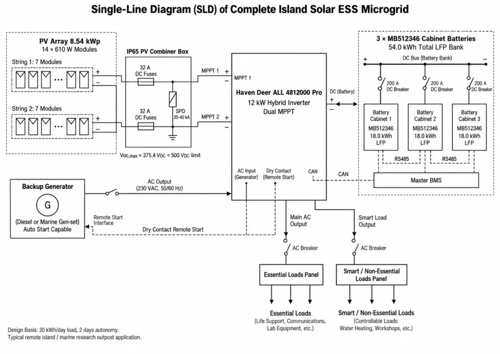
The single-line diagram (SLD) routes 8.54kWp PV power through an outdoor IP65 combiner box equipped with 32A DC fuses and a 20–40kA surge protective device (SPD) into the dual MPPT inputs of the ALL 4812000 Pro inverter.
The battery DC circuit uses 200A-rated DC breakers to connect the 3 × MB512346 mobile cabinet batteries in parallel. Closed-loop CAN bus links the Master BMS cabinet to the inverter, while slave cabinets daisy-chain via RS485 communication lines.
The Main AC Output feeds the essential distribution panel, while the Smart Load Output powers shed-able non-essential circuits. Dry contact terminals route via a two-wire circuit to the backup generator remote-start module.
Engineering Consultation Notice: Multi-input off-grid microgrids require exact load profiling, environmental analysis, and hardware matching. Contact the Haven Deer engineering team for custom single-line diagrams, project sizing validation, and system configuration support.
7. Installation, Safety Protocols, and Commissioning Checklist
Executing a standardized commissioning checklist for installers during first-time setup prevents hardware damage, verifies electrical safety, and validates closed-loop BMS-to-inverter communication. Systematic checks prevent costly field failures.
7.1 Pre-Commissioning Verification & Closed-Loop Communication Setup
Execute the following 6-step commissioning protocol before energizing the microgrid:
[Step 1] Verify Mechanical Installation & Enclosure Clearance .
[Step 2] Measure DC Open-Circuit Voltage & Polarity of PV Strings .
[Step 3] Configure Battery Address DIP Switches (Master = 1, Slaves = 2–6) .
[Step 4] Verify CAN / RS485 Communication Wiring Integrity .
[Step 5] Apply DC Battery Power First to Boot Inverter EMS Control.
[Step 6] Activate Solar PV & Generator AC Inputs; Verify Parameter Sync .
- Mechanical Inspection: Lock cabinet caster brakes and verify level, load-bearing floor placement. Adequate ventilation clearance prevents thermal throttling.
- DC Polarity & Voltage Check: Measure open-circuit voltage (Voc) and verify polarity across incoming PV strings and DC battery leads using a DMM before throwing DC breakers.
- Master-Slave DIP Address Mapping: Set BMS DIP switches prior to parallel wiring. Program the inverter-connected pack as Address 1 (Master) and assign sequential addresses (2–6) to slave packs.
- Communication Cable Connection: Run the CAN/RS485 cable from Master BMS to the inverter BMS port. Daisy-chain slave batteries sequentially across communication ports.
- Initial Battery Boot (Lithium Activation): Close the DC battery breaker first to power inverter EMS logic and establish BMS comms. For deeply discharged banks, trigger the inverter’s PV or generator lithium activation feature.
- Parameter Synchronization: Confirm BMS communication via the inverter LCD or application interface. Verify that telemetry data—protocol, SoC, voltage, and current limits—matches physical pack status.
Common Engineering Mistake: Setting duplicate DIP addresses on parallel battery packs. Addressing conflicts disrupt CAN/RS485 comms and corrupt SoC telemetry.
7.2 Preventive Maintenance Protocols for Long-Term Autonomy
LiFePO4 batteries and hybrid inverters demand far less maintenance than lead-acid or diesel systems, but routine servicing ensures multi-year reliability:
- Thermal & Vent Inspection: Clear intake grilles and dust filters on inverters and battery cabinets. Unrestricted airflow prevents thermal derating.
- Torque Verification: De-energize system buses and check terminal torque on high-current DC studs, busbars, and AC lugs. Re-torquing prevents hot spots caused by thermal cycling.
- Combiner Box Service: Inspect outdoor IP65 combiner boxes for condensation, check DC SPD fault indicators, and test string fuse continuity.
- Firmware & Log Verification: Audit EMS event logs via the monitoring app. Confirm stable system dispatch and verify auto-start dry contact logs.
8. Technical Frequently Asked Questions (FAQ)
1. How does an off-grid solar ESS maintain continuous power during multi-day storms on an island?
Off-grid systems withstand multi-day storms by pairing battery autonomy with automated genset backup. When battery SoC hits the low setpoint (e.g., 20%), the inverter EMS closes a passive dry contact to auto-start the generator. Continuous AC power prevents site blackouts.
2. Can Haven Deer hybrid inverters operate completely without a utility grid connection?
Yes. Haven Deer ALL 486000 Pro and ALL 4812000 Pro hybrid inverters operate completely off-grid. They integrate MPPT tracking, pure sine wave AC synthesis, BMS comms, and generator controls into a single microgrid Energy Hub. Autonomous control ensures grid independence.
3. What is the benefit of Dual Independent MPPT trackers for island solar arrays?
Dual MPPT channels optimize PV strings mounted at different tilts, azimuths, or partial shading conditions independently. Separate MPPT tracking maximizes array energy yield on complex roofs or rugged terrain. Independent tracking eliminates mismatch losses.
4. Why are mobile cabinet batteries preferred over wall-mounted batteries for remote outposts?
Floor-standing cabinet batteries (MB512300 15kWh / MB512346 18kWh) rest directly on equipment room floors, eliminating structural wall-load limits. Heavy-duty casters simplify positioning in tight shelters. Floor mounting prevents structural wall failure.
5. How does salt mist affect island solar energy storage installations?
Airborne salt mist corrodes copper terminals, busbars, and exposed circuit traces. Off-grid systems block corrosion using outdoor IP65 combiner boxes, housing IP21/IP22 gear in dry shelters, and specifying conformal-coated PCBs. Conformal coating prevents salt-mist short circuits.
6. What transfer time is required to prevent server shut-downs at remote research stations?
Sensitive IT gear and servers require under 16ms switching to prevent rebooting. Haven Deer hybrid inverters deliver 10ms UPS-grade transfer times on critical load outputs. Fast transfer prevents server crashes.
7. How does low ambient temperature affect LiFePO4 battery charging in remote areas?
Charging LiFePO4 cells below 0°C causes lithium plating, short-circuiting internal cell layers. The integrated BMS blocks charging at sub-zero temperatures while permitting discharge down to -15°C or -20°C. Temperature cutoffs preserve battery lifespan.
8. Can multiple Haven Deer hybrid inverters be connected in parallel for larger microgrids?
Yes. Haven Deer hybrid inverters support multi-unit parallel operation. Installers stack multiple inverters across shared AC and DC buses to scale system AC output capacity. Parallel stacking scales microgrid capacity cleanly.
9. What generator specifications are required for dry contact auto-start integration?
Standby gensets require keyless electric start capabilities and two-wire remote control terminals compatible with voltage-free dry contacts. Generator output voltage and frequency (50Hz/60Hz) must match inverter AC input specs. Two-wire compatibility enables automated auto-start.
10. How does Dual AC Output protect essential loads during power deficits?
Dual AC outputs split site wiring into essential circuits and smart, shed-able loads. The Main Output carries essential comms and refrigeration, while the Smart Load Output powers non-essential HVAC or water heaters. Load shedding extends emergency battery autonomy.
11. What is the standard lifespan of Haven Deer Grade A LiFePO4 battery cabinets?
Haven Deer Grade A LiFePO4 cabinets deliver long operational lifespans off-grid. Tested at 25°C, they achieve ≥6,000 cycles at 90% DoD and ≥10,000 cycles at 80% DoD. Deep cycling yields 15+ years of service.
12. What international safety standards apply to Haven Deer off-grid ESS hardware?
Haven Deer off-grid ESS equipment complies with international electrical safety, grid-code, and EMC standards, including CE, UN38.3, and IEC requirements. Certified compliance ensures safe global deployment.
9. Request an Engineering Consultation
Deploying off-grid solar ESS in island microgrids, remote outposts, or commercial facilities requires precise system engineering. Haven Deer application engineers deliver technical support for load sizing, electrical design, and hardware selection. Direct engineering support eliminates field design errors.
Our application engineering team assists system integrators and project engineers with:
- Custom Load Profiling & Battery Autonomy Sizing: Match battery capacity to site load curves and weather profiles.
- Single-Line Diagram (SLD) Design & Electrical System Review: Verify breaker ratings, wire gauges, and busbar schematics.
- Generator Auto-Start Integration Assessment: Configure dry-contact relays for two-wire remote start compatibility.
- System Hardware Configuration & B2B Project Support: Validate inverter-to-battery matching prior to site deployment.
Contact Haven Deer Engineering for a Custom System Evaluation