Quick Answer: Low-temperature charging protection (0°C cutoff) is a hardware and firmware safeguard implemented by a Battery Management System (BMS) that prevents charging current from entering Lithium Iron Phosphate (LiFePO₄) cells when the minimum cell temperature drops to 0°C or below. At sub-zero temperatures, lithium-ion intercalation into the graphite anode slows down significantly. Applying charging current under these conditions can cause metallic lithium plating on the anode surface, resulting in irreversible capacity loss, internal micro-short circuits, and potential cell safety risks. While LiFePO₄ battery discharge operation can remain chemically stable down to -15°C or -20°C depending on battery enclosure design, charging requires strict low-temperature lockout mechanisms to protect battery health.
1. The Electrochemical Physics of Sub-Zero Charging in LiFePO4 Cells
Understanding why Lithium Iron Phosphate (LiFePO₄) chemistry requires a strict 0°C charging lockout is an essential part of designing reliable off-grid solar ESS systems in sub-zero climates, where battery chemistry, temperature limits, and system protection strategies directly affect long-term performance.
During a standard charging cycle above 15°C, lithium ions (Li⁺) de-intercalate from the olivine cathode structure, migrate through the liquid electrolyte, cross the microporous separator, and intercalate cleanly into the layered graphite anode. This process depends on two main factors: high ionic conductivity within the organic electrolyte and rapid charge-transfer kinetics at the graphite electrode interface.
+-----------------------------------------------------------------------+
|                        NORMAL CHARGING (> 15°C)                       |
|                                                                       |
|   Cathode (LiFePO₄)  --->  Electrolyte  --->  Anode (Graphite)        |
|                           (Low Viscosity)    (Rapid Intercalation)    |
|                                                                       |
|   Result: Safe Li⁺ insertion into carbon lattice.                     |
+-----------------------------------------------------------------------+
|                       SUB-ZERO CHARGING (≤ 0°C)                       |
|                                                                       |
|   Cathode (LiFePO₄)  --->  Electrolyte  --->  Anode Surface           |
|                           (High Viscosity) (High Rct / Slow Diffusion)|
|                                                                       |
|   Result: Metallic Lithium Plating (Li⁰) on Anode Surface!            |
+-----------------------------------------------------------------------+
When cell temperatures drop toward and below 0°C, three distinct electrochemical obstacles emerge:
- Electrolyte Viscosity Increase: The liquid organic solvent (typically carbonate-based blends) becomes increasingly viscous, significantly decreasing ionic conductivity and increasing bulk electrolyte resistance.
- Elevated Charge-Transfer Resistance (Rct): The kinetic energy required for lithium ions to shed their solvation shell and cross the Solid Electrolyte Interphase (SEI) layer increases exponentially.
- Reduced Solid-State Diffusion: The diffusion coefficient of lithium ions inside the graphite lattice drops dramatically, restricting the speed at which ions can insert themselves between carbon layers.
The relationship between temperature and reaction rate kinetics is described by the Arrhenius equation:
k = A × e^(-Ea / (R × T))
Where:
- k = Reaction rate constant for lithium-ion transfer
- A = Pre-exponential frequency factor
- Ea = Activation energy for lithium intercalation into graphite (J/mol)
- R = Universal gas constant (8.314 J/(mol·K))
- T = Absolute cell temperature in Kelvin (K)
As temperature (T) drops, the reaction rate constant (k) decreases exponentially. Because lithium-ion diffusion inside the graphite anode cannot keep pace with the applied charging current, lithium ions accumulate at the anode boundary layer instead of intercalating safely into the carbon matrix.
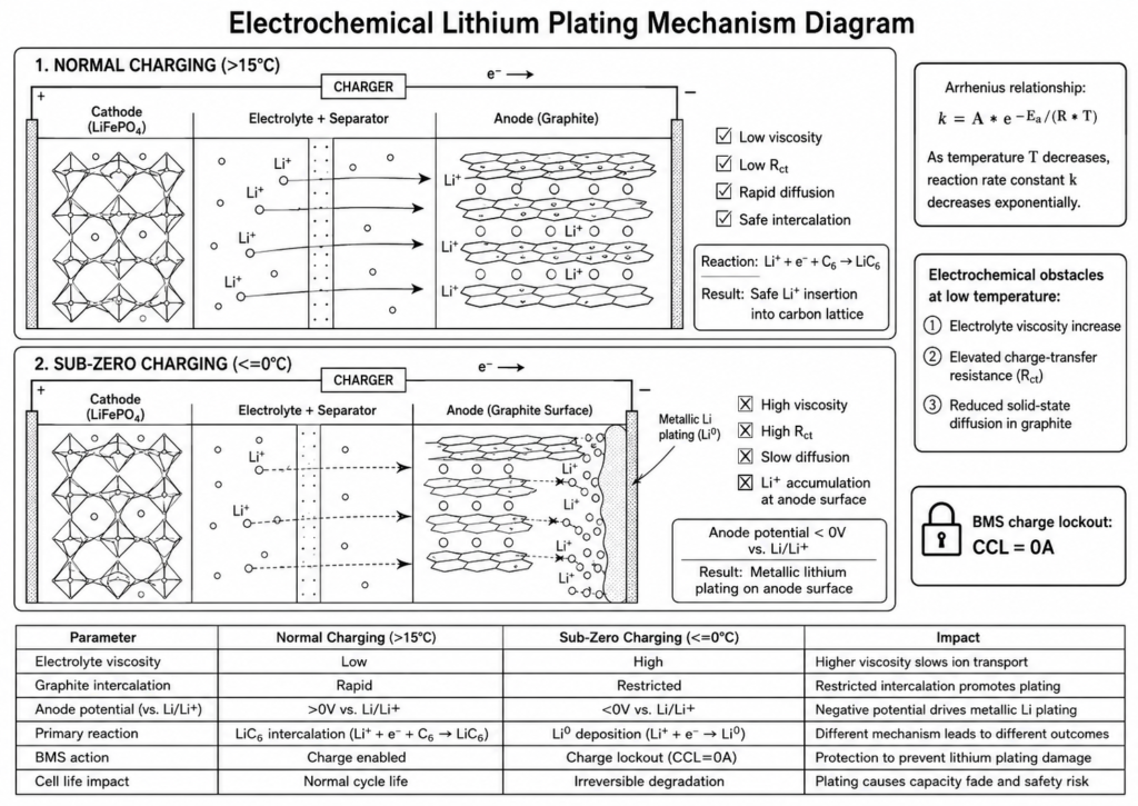
| Operational Parameter | Normal Temperature Range (15°C to 35°C) | Sub-Zero Range (≤ 0°C) |
|---|---|---|
| Electrolyte Viscosity | Low (Optimal ionic mobility) | High (Reduced ionic mobility) |
| Graphite Intercalation | Rapid & efficient | Severely sluggish / Restricted |
| Anode Potential (E_anode) | > 0V vs. Li/Li⁺ (Safe) | < 0V vs. Li/Li⁺ (Plating Risk) |
| Primary Chemical Reaction | Li⁺ + e⁻ + C₆ ──► LiC₆ | Metallic Li⁰ deposition on anode surface |
| BMS Action Status | Normal Charge Enabled (CCL > 0A) | Charge Lockout Enforced (CCL = 0A) |
| Impact on Cell Life | Standard cycle life (≥ 6000–10000 cycles) | Accelerated, irreversible capacity loss |
2. The Danger of Metallic Lithium Plating & Permanent Cell Degradation
When an external power source—such as a solar PV array, utility grid charger, or AC generator—applies charging current to a sub-zero LiFePO₄ cell, increased electrochemical polarization can drive the local potential of the graphite anode below the lithium plating threshold:
E_anode < 0V vs. Li/Li⁺
When this potential threshold is crossed, incoming lithium ions can accept electrons at the outer surface of the graphite particles instead of intercalating into the graphite structure. This converts ionic lithium (Li⁺) into solid, metallic lithium (Li⁰)—a process known as metallic lithium plating.
  [ Incoming Charge Current ]
               │
               ▼
  [ Anode Surface (≤ 0°C) ] ──► Overpotential drives E_anode < 0V vs. Li/Li⁺
               │
               ├─► 1. Metallic Lithium Plating (Li⁰ Accumulation)
               ├─► 2. Dendrite Growth (Pierces Separator)
               └─► 3. Irreversible Loss of Active Lithium (Capacity Fade)
Lithium plating causes two main types of system degradation:
2.1 Irreversible Capacity Fade (Loss of Active Lithium)
Plated metallic lithium is highly reactive and can react with the surrounding organic electrolyte, forming additional Solid Electrolyte Interphase (SEI) products. This permanently consumes active lithium ions from the cell's electrochemical inventory. Even after the battery is subsequently warmed, part of the plated lithium can remain electrochemically isolated as "dead lithium," contributing to irreversible capacity loss.
2.2 Internal Micro-Short Circuits and Dendrite Formation
Under unfavorable charging conditions, metallic lithium can deposit unevenly and may develop into microscopic filament-like structures commonly described as lithium dendrites. Over repeated sub-zero charging events, these dendrites grow outward from the graphite anode across the separator gap. If such structures continue to grow, they may penetrate the microporous separator and create an internal conductive path between the anode and cathode. This causes internal self-discharge, localized hot spots, micro-short circuits, and potential cell failure.
CRITICAL SAFETY DISTINCTION: LiFePO₄ batteries can continue discharging at sub-zero temperatures within their specified operating range—down to -15°C for Haven Deer wall-mounted batteries and -20°C for floor-standing mobile cabinet batteries—because discharge moves lithium ions away from the graphite anode toward the cathode. In contrast, charging forces ions into the sluggish anode. Charging at or below 0°C without effective BMS charge lockout or thermal pre-heating can cause irreversible lithium plating and permanent capacity loss.
3. BMS Low-Temperature Sensing, Logic & Cutoff Mechanism
To protect prismatic Grade A LiFePO₄ cells from low-temperature charging damage, the integrated Battery Management System (BMS) monitors battery temperature and applies low-temperature charge protection through its control logic.
       [ Battery Temperature Sensors ]
                      │
                      ▼
            [ BMS Control Logic ]
                      │
       ┌──────────────┴──────────────┐
       ▼                             ▼
 T_cell ≤ 0°C                       T_cell > Recovery Threshold
[Trigger Charge Lockout]          [Clear Lockout State]
 (Charging Disabled)               (Charging Re-enabled)
3.1 Hardware Temperature Sensing Architecture
The BMS uses internal temperature sensors to monitor battery thermal conditions and detect when charging must be restricted because of low cell temperature:
- Internal Temperature Monitoring: Temperature sensors monitor thermal conditions within the battery pack so the BMS can enforce high- and low-temperature protection.
- Low-Temperature Detection: The BMS evaluates internal battery temperature rather than relying solely on external ambient temperature.
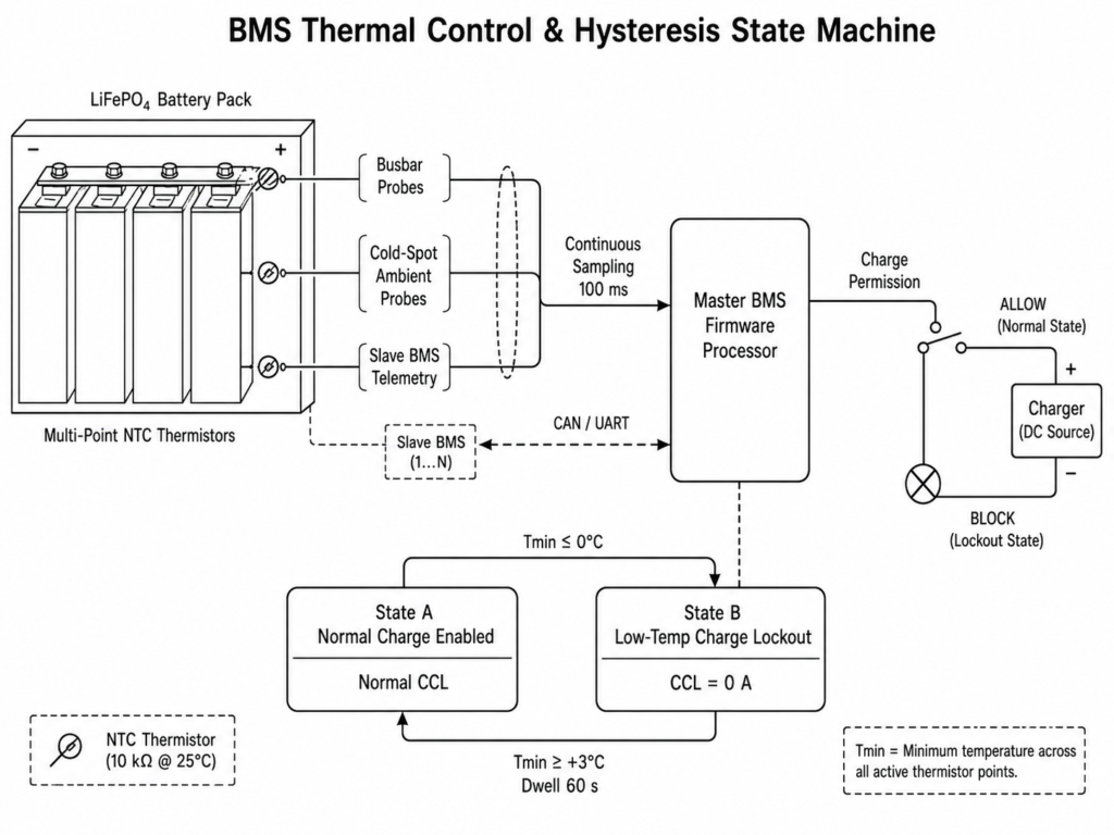
- Master-Slave Coordination: In multi-pack parallel configurations, each battery pack retains its own BMS protection functions, while the Master BMS aggregates battery status and communicates system-level battery information to the hybrid inverter.
3.2 Hysteresis Control State Machine
To prevent repeated switching between charge-enabled and charge-disabled states when battery temperature remains close to the cutoff threshold, the BMS can use a temperature hysteresis band:
- Low-Temperature Charge Cutoff Trigger: When the monitored battery temperature reaches 0°C or below, the BMS activates low-temperature charge protection and disables charging.
- Hysteresis Recovery Threshold: Charging remains disabled until the monitored battery temperature rises above the configured recovery threshold, after which the BMS can restore normal charging permission.
ENGINEERING TIP: Do not rely solely on ambient room temperature when determining whether a LiFePO₄ battery is safe to charge. Battery temperature can lag behind changes in surrounding air temperature, so charging permission should be based on the battery’s internal BMS temperature protection status.
4. Closed-Loop Protocol Flow: BMS to Hybrid Inverter (EMS) Control
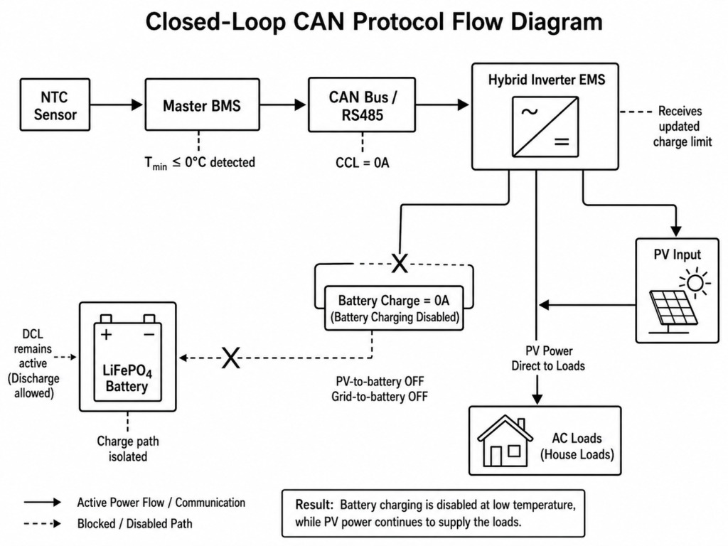
In an integrated solar energy storage system, the BMS communicates battery status and protection information to the hybrid inverter through closed-loop CAN or RS485 communication, allowing the inverter’s Energy Management System (EMS) to coordinate charging and system-level energy flow.
+-----------------------------------------------------------------------+
|                    CLOSED-LOOP COMMUNICATION FLOW                     |
|                                                                       |
|  [ Temperature Sensor ] ---> [ BMS ] ---> [ CAN / RS485 ]             |
|                                                  |                    |
|                                                  v                    |
|                                      [ Hybrid Inverter / EMS ]        |
|                                           |                  |        |
|                                           v                  v        |
|                                  [ Battery Charge ]   [ AC Loads ]    |
|                                  [ Restricted/Off ]                   |
+-----------------------------------------------------------------------+
Step-by-Step Data Control Sequence
- Temperature Detection: The BMS detects that the monitored battery temperature has reached 0°C or below and activates low-temperature charge protection.
- Protection Data Transmission: The BMS communicates the low-temperature charge restriction to the hybrid inverter through the configured CAN or RS485 protocol, instructing the inverter to stop battery charging while discharge remains available within the battery’s permitted operating range.
- Inverter EMS Execution: The hybrid inverter, such as the Haven Deer ALL 4812000 Pro or ALL 486000 Pro, receives the low-temperature charging restriction from the BMS through the closed-loop communication link.
- Battery Charging Suspension: The inverter responds by stopping charging energy from being routed to the battery from available PV or AC charging sources.
- Load Supply Continuity: If sufficient solar PV generation is available, the hybrid inverter can continue supplying connected AC loads from PV while battery charging remains disabled, subject to the selected operating mode, available PV power, and instantaneous load demand.
COMMON MISTAKE: Operating a LiFePO₄ battery without closed-loop CAN/RS485 communication in freezing climates requires additional caution. If the inverter cannot receive battery temperature and protection data from the BMS, charging control may rely primarily on configured voltage and current limits. Low-temperature charging protection must therefore be enforced locally by the battery BMS or by another validated control method to prevent charging at unsafe cell temperatures.
5. Cold-Climate Engineering: Discharge Rules vs. Charge Lockouts
Designing off-grid and residential solar ESS installations for cold climates like Eastern Europe, Central Asia, or high-altitude regions requires separating charging limits from discharging capabilities.
5.1 Enclosure Engineering & Thermal Operating Windows
Haven Deer wall-mounted and floor-standing mobile cabinet batteries have different enclosure protection ratings and specified temperature operating ranges. The AL-WM512100 and AL-WM512200 wall-mounted batteries are rated IP21 with discharge operation down to -15°C, while the MB512300 and MB512346 floor-standing mobile cabinet batteries are rated IP22 with discharge operation down to -20°C. Battery system safety design should also consider applicable standards such as IEC 62619, while hybrid inverter safety requirements are covered by standards including IEC 62109-1 and IEC 62109-2.
| Product Series | Form Factor & Protection | Charge Temp Range | Discharge Temp Range | Storage Temp Window |
|---|---|---|---|---|
| AL-WM512100 / AL-WM512200 | Wall-Mounted (IP21) | 0°C to 50°C | -15°C to 50°C | -15°C to 50°C |
| MB512300 / MB512346 | Floor-Standing Mobile Cabinet (IP22) | 0°C to 55°C | -20°C to 55°C | -15°C to 50°C |
5.2 Practical Installation & Commissioning Guidelines
COLD-WEATHER SITE DESIGN CHECKLIST
[✓] Install battery bank inside a climate-controlled equipment room
[✓] Maintain installation clearances specified for the enclosure
[✓] Connect CAN/RS485 closed-loop communication cables to inverter
[✓] Configure Dry Contact generator auto-start where required
[✓] Verify BMS temperature monitoring before commissioning
- Indoor Protected Placement: Install Haven Deer IP21 wall-mounted batteries and IP22 floor-standing mobile cabinet batteries in suitable indoor equipment spaces protected from direct weather exposure. For cold regions, insulated equipment rooms and battery storage pre-heating strategies for cold equipment rooms can help maintain battery temperature within the specified charging range.
- Internal Joule Heating During Discharge: Battery discharge produces resistive heat because current flows through the internal resistance of the cells. This heat may contribute to a gradual rise in battery temperature, but charging must remain disabled until the BMS confirms that the battery has returned to its permitted charging temperature range.
- Automated Generator Integration via Dry Contact: During extended winter overcast periods when battery SOC falls to the configured threshold, the hybrid inverter can use its Dry Contact relay to signal a compatible diesel or gas generator to start. Generator power can then enter the hybrid inverter through the AC input to support connected loads, while battery charging remains restricted by the BMS until the battery returns to its permitted charging temperature range.
6. Frequently Asked Questions (Technical FAQ)
Why cannot Lithium Iron Phosphate (LiFePO4) batteries charge below 0°C?
At or below 0°C, lithium-ion diffusion within the graphite anode slows down and electrolyte resistance increases. Applying charging current under these conditions can cause lithium plating on the anode surface instead of normal lithium-ion intercalation, resulting in irreversible capacity loss and increased cell degradation risks.
Can a LiFePO4 battery discharge at sub-zero temperatures?
Yes. Discharging moves lithium ions from the graphite anode toward the cathode and does not create the same lithium plating mechanism associated with low-temperature charging. Haven Deer wall-mounted battery systems support discharge operation down to -15°C, while floor-standing mobile cabinet systems support discharge operation down to -20°C.
What happens if an unmanaged solar charger forces current into an LFP battery at -5°C?
Without BMS low-temperature charge protection, applying charging current to a sub-zero cell can create conditions that promote lithium plating on the anode surface. Repeated lithium plating events can reduce active battery capacity and may increase the risk of internal cell degradation.
How does the Haven Deer BMS enforce the 0°C charge lockout?
The battery BMS continuously monitors internal battery temperature. When the measured temperature reaches the configured low-temperature charge cutoff threshold, the BMS communicates charging restrictions through the CAN/RS485 connection to the hybrid inverter. The inverter then stops battery charging while maintaining permitted discharge operation.
What is temperature hysteresis in BMS protection logic?
Temperature hysteresis prevents repeated switching between charging enabled and disabled states when battery temperature remains close to the cutoff threshold. After low-temperature charge protection is triggered, the BMS requires the battery temperature to rise above the configured recovery threshold before charging permission is restored.
Can solar panels still power home loads when battery charging is locked out due to cold?
Yes. Under closed-loop CAN/RS485 control, the hybrid inverter receives battery charging restrictions from the BMS and stops directing PV power or AC charging power into the battery. Available solar PV power can continue supplying connected loads depending on system configuration, operating mode, and available generation.
Are integrated battery heating pads required for sub-zero installations?
For installations exposed to severe winter conditions without temperature-controlled environments, thermal insulation or battery pre-heating solutions may be required. Pre-heating systems can raise battery temperature above the charging cutoff threshold before normal charging is permitted by the BMS.
Does discharging a cold battery help warm it up for safe charging?
Yes. Battery discharge generates internal heat through resistive losses (I²R) as current flows through the cells. In some cold environments, this heat generation may help increase battery temperature, but charging is only permitted after the BMS confirms that the battery has returned to an acceptable charging temperature range.
What is the difference between IP21 wall-mounted and IP22 floor-standing cabinet batteries in cold environments?
Both enclosure types are designed for indoor energy storage installations. Floor-standing mobile cabinet models provide a wider discharge temperature range down to -20°C compared with wall-mounted models, making them suitable for larger residential, agricultural, and light commercial applications.
How should LFP batteries be prepared for long-term winter storage?
If an off-grid facility is shut down during winter, disconnect the battery system at approximately 40% to 60% State of Charge (SOC). Store the batteries within their specified storage temperature range and isolate automatic charging sources when storage conditions may allow charging below the permitted temperature range.
7. Planning an Off-Grid Solar Project for Sub-Zero Climates?
Building reliable off-grid and residential energy storage systems in cold climates requires coordinated design across LiFePO₄ batteries, hybrid inverters, BMS protection logic, and thermal management strategies.
Haven Deer provides engineering-focused Solar Energy Storage System (ESS) solutions integrating Grade A LiFePO₄ batteries, closed-loop BMS protection, hybrid inverter control, and automated generator integration for cold-climate applications.