Quick Answer: Sub-zero off-grid solar energy storage system (ESS) performance depends on three critical engineering controls: enforcing a 0°C battery charging cutoff through the Battery Management System (BMS) to prevent lithium plating, calculating cold-weather PV string open-circuit voltage (Voc) to remain below the inverter’s 500V DC maximum input limit, and using passive dry-contact generator automation to maintain power availability during extended winter solar shortages.
Reliable off-grid operation in cold regions requires coordinated management of battery electrochemistry, thermal conditions, photovoltaic generation, and multi-input energy control.
1. The Physics of Sub-Zero Operations on Solar ESS Architecture
Sub-zero ambient temperatures change the operating characteristics of every major subsystem within an off-grid solar energy storage system. Cold conditions increase photovoltaic module voltage output due to the negative temperature coefficient of PV cells, while simultaneously reducing battery electrochemical activity, increasing internal resistance, and affecting overall system performance.
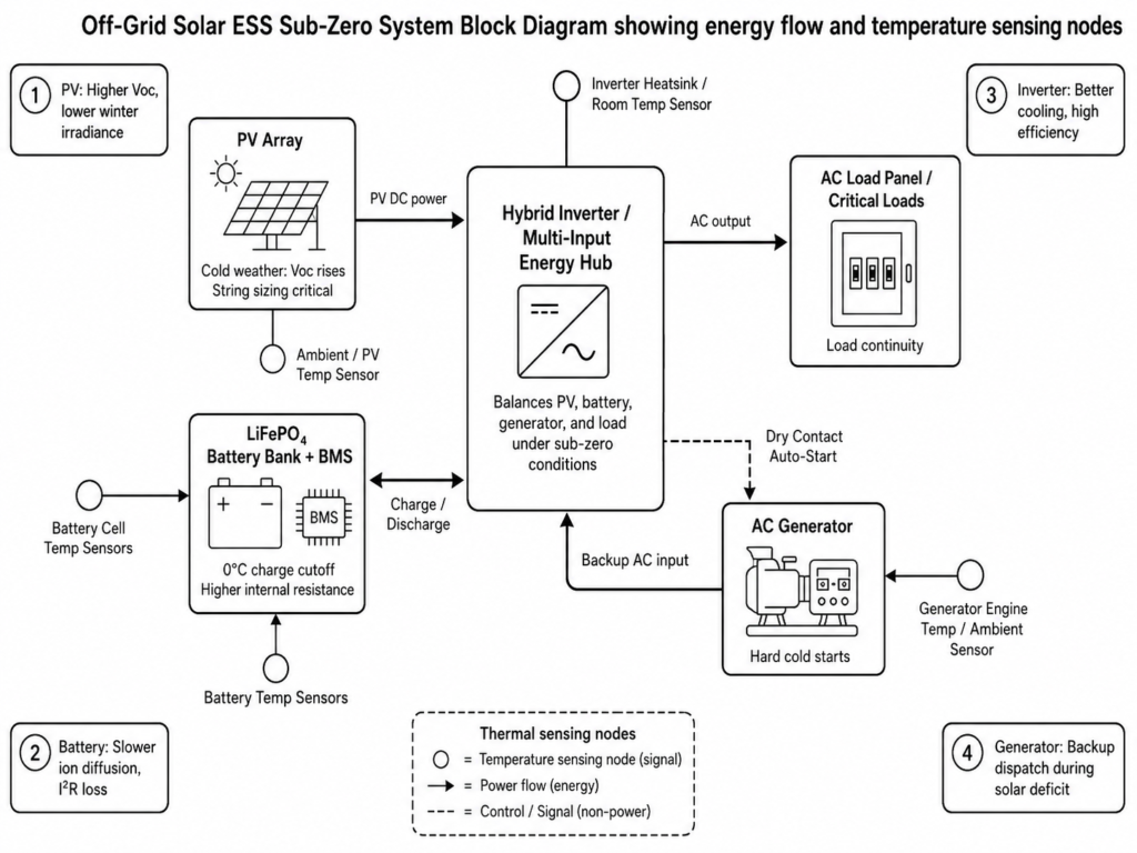
At the core of an off-grid installation is the hybrid inverter operating as an intelligent Multi-Input Energy Hub. During sub-zero operation, the inverter EMS continuously coordinates four dynamic system conditions:
- Photovoltaic Generation Spikes: Lower ambient temperatures increase PV module open-circuit voltage (Voc) due to the negative temperature coefficient, while winter cloud cover and shorter daylight hours reduce total daily solar energy production.
- Electrochemical Resistance Rise: Lower cell temperatures reduce lithium-ion diffusion efficiency, causing temporary capacity reduction, increased internal resistance, and greater voltage sag under high discharge loads.
- Inverter Thermal Performance: Cold ambient conditions improve heat dissipation from power electronics, reducing thermal stress during operation while maintaining normal conversion efficiency within rated operating conditions.
- Auxiliary Energy Dispatch: Extended winter solar shortages require reliable backup energy coordination, with AC generators automatically triggered through dry contact signals to maintain essential load operation.
| Subsystem | Sub-Zero Thermal Impact | Primary Operational Risk | Engineering Mitigation |
|---|---|---|---|
| PV Array | Higher open-circuit voltage (Voc) output | MPPT input overvoltage damage (>500V DC) | Cold-weather string sizing calculations |
| LiFePO4 Storage | Reduced ionic conductivity and electrolyte mobility | Anode lithium plating during sub-zero charging | BMS thermal sensing and 0°C charge cutoff |
| Hybrid Inverter | Improved heat dissipation from power electronics | Condensation risk during temperature changes | Indoor IP21 installation in a dry and ventilated equipment room |
| AC Generator | Cold-weather starting difficulty and frequency/voltage instability | Power interruption during generator transfer | Automated dry contact control with UPS-level transfer support |
Understanding these interactions is essential for reliable operation during prolonged freezing conditions. An off-grid solar ESS functions as an integrated energy ecosystem where battery temperature limits, PV voltage behavior, and EMS control logic determine system power routing decisions. For a complete overview of system architecture, see our guide to Modern Off-Grid Solar ESS Kit Architecture.
2. LiFePO4 Battery Behavior in Sub-Zero Temps: Chemical Limits & BMS Protections
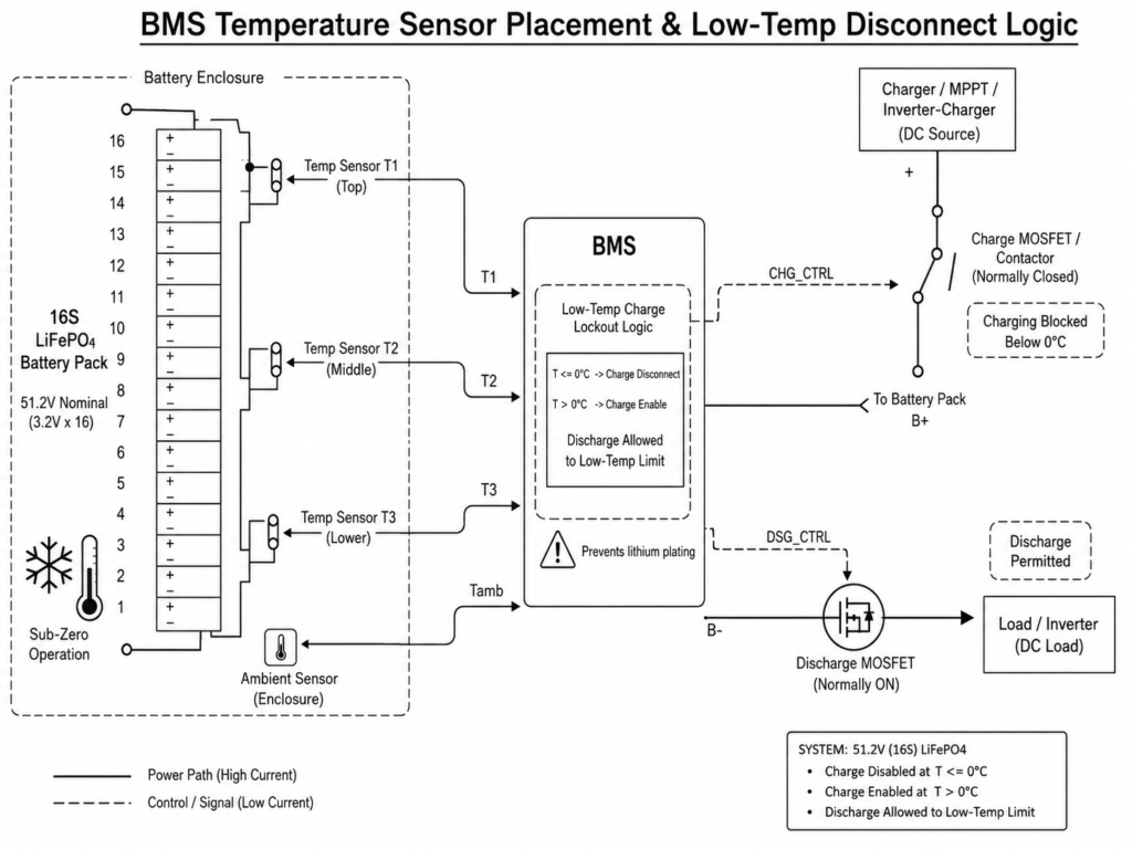
Lithium Iron Phosphate (LiFePO4) chemistry is widely used in residential and light commercial energy storage systems because of its thermal stability, structural safety, and long cycle life. However, charging LiFePO4 cells below 0°C can cause lithium plating risks, requiring active protection from the Battery Management System (BMS).
2.1 The Physics of Low-Temperature Charging & Lithium Plating
At normal operating temperatures (approximately 25°C), lithium ions can efficiently intercalate into the graphite anode during charging. When cell temperatures fall below 0°C, lithium-ion diffusion becomes significantly slower, reducing the ability of the anode to absorb incoming lithium ions. If charging continues under these conditions, metallic lithium can deposit on the anode surface, a process known as lithium plating.
Lithium plating causes three major operational problems:
- Permanent Capacity Loss: Metallic lithium deposits can become inactive, reducing the available lithium inventory and permanently decreasing usable battery capacity.
- Internal Short-Circuit Risk: Continued lithium plating may create metallic structures that increase the possibility of separator damage and internal short circuits.
- Cell Safety Risk: While LiFePO4 chemistry has strong intrinsic thermal stability, severe cell damage caused by uncontrolled lithium plating can increase operational risks.
To prevent this mechanism, intelligent BMS platforms enforce a 0°C charging cutoff. When temperature sensors detect cell temperatures at or below 0°C, the BMS disables the charging path while allowing discharge operation within the battery’s temperature limits. Learn more about LiFePO4 Low-Temperature Charging Protection with 0°C Cutoff.
2.2 Sub-Zero Discharging Dynamics & Limits
Unlike charging, LiFePO4 battery discharge operation can continue at lower temperatures within the specified operating range because it does not introduce the same lithium plating mechanism.
During discharge, lithium ions move in the reverse direction through the cell structure, and the reaction does not create metallic lithium deposition on the anode.
However, sub-zero discharge operation increases internal resistance, causing greater voltage sag during high-current loads. For example, a 200A continuous discharge from a cold battery bank will produce a lower terminal voltage than the same load at 25°C. The BMS and EMS must monitor this voltage behavior to prevent unnecessary low-voltage shutdowns. Learn more about Low-Temperature LFP Battery Discharge Performance Down to -15°C / -20°C.
| Parameter / Operational Window | Wall-Mounted LFP Series (AL-WM512100 / AL-WM512200) | Floor-Standing Mobile Cabinet Series (MB512300 / MB512346) |
|---|---|---|
| Nominal Voltage & Architecture | 51.2V (16S Grade A Prismatic Cells) | 51.2V (16S Grade A Prismatic Cells) |
| Charge Temperature Range | 0°C to 50°C (BMS 0°C Cutoff Enforced) | 0°C to 55°C (BMS 0°C Cutoff Enforced) |
| Discharge Temperature Range | -15°C to 50°C | -20°C to 55°C |
| Enclosure Protection Rating | IP21 (Indoor Wall-Mounted) | IP22 (Indoor Mobile Cabinet) |
| Cycle Life Performance | ≥6,000 cycles (90% DOD) / ≥10,000 cycles (80% DOD) | ≥6,000 cycles (90% DOD) / ≥10,000 cycles (80% DOD) |
| Performance Metric | Grade A LiFePO4 Storage Systems | Traditional Lead-Acid / AGM Batteries |
|---|---|---|
| Usable Capacity at -10°C | ~75% to 80% nominal energy | ~40% to 50% nominal energy |
| Freezing Fluid Risk | No liquid electrolyte freezing mechanism in LiFePO4 cells | Lead-acid electrolyte can freeze when deeply discharged, creating potential enclosure damage |
| Cycle Life in Cold Weather | ≥6,000–10,000 cycles under specified test conditions with BMS protection | Reduced cycle life due to accelerated sulfation and cold-weather performance degradation |
| BMS Automation | Closed-loop CAN/RS485 temperature protection | Open-loop manual load management required |
Engineering Tip: When installing 51.2V wall-mounted modules such as the AL-WM512200 (10.24kWh) or floor-standing cabinet batteries such as the MB512346 (18.0kWh) in freezing environments, place the equipment inside a thermally insulated indoor space. If the room temperature remains below 0°C for extended periods, consider using a thermostatically controlled heating solution powered by an auxiliary AC source to maintain suitable battery temperatures and allow normal solar charging when conditions permit.
3. Cold-Weather PV String Array Design & Voc Voltage Rise Calculations
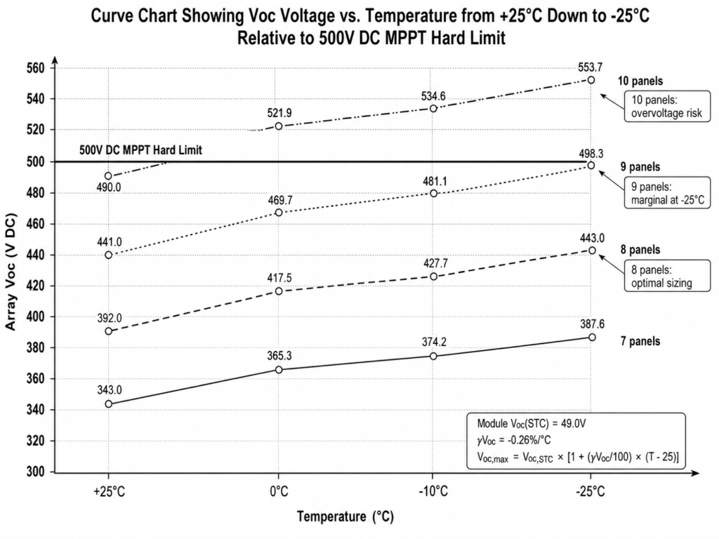
A common failure mode in cold-climate off-grid solar systems is MPPT overvoltage caused by incorrect PV string sizing. Photovoltaic modules have a negative temperature coefficient of open-circuit voltage (γVoc), meaning the module Voc increases as cell temperature drops below Standard Test Conditions (STC = 25°C).
3.1 Cold-Weather Voltage Formula
To ensure the PV string voltage remains below the hybrid inverter’s maximum MPPT input limit, engineers must calculate the maximum cold-weather open-circuit voltage (Voc,max) based on the minimum expected ambient temperature (Tmin):
Voc,max = Voc,STC × [1 + (γVoc / 100) × (Tmin – 25)]
Where:
- Voc,max: Calculated open-circuit voltage of the PV module at the minimum design temperature (V).
- Voc,STC: Rated open-circuit voltage of the module at 25°C (V).
- γVoc: Temperature coefficient of Voc (%/°C), expressed as a negative percentage.
- Tmin: Local historical minimum record ambient temperature (°C).
For detailed PV string voltage calculations and winter design margins, see our guide on Calculating Cold-Weather Voc Safety Margins.
3.2 Step-by-Step Worked Sizing Example
Consider a cold-climate system deployed in Eastern Europe using 610W Monocrystalline PV Modules paired with the ALL 4812000 Pro 12kW Hybrid Solar Inverter.
- Equipment Specifications:
- PV Module: 610W Mono (Voc,STC = 49.0V, γVoc = -0.26%/°C).
- Inverter Specs: Max PV Input Voltage = 500V DC, MPPT Operating Range = 60V to 500V DC.
- Site Design Condition: Minimum ambient temperature (Tmin) = -25°C.
Step 1: Calculate single module Voc at -25°C
Temperature Delta (ΔT) = -25°C – 25°C = -50°C
Voltage Multiplier = 1 + [(-0.26 / 100) × (-50)]
Voltage Multiplier = 1 + [-0.0026 × -50] = 1 + 0.13 = 1.13
Voc(-25°C) = 49.0V × 1.13 = 55.37V DC per panel
Step 2: Determine maximum safe panels in series per MPPT string
Max Series Panels = Maximum Inverter Voltage Limit / Voc(-25°C)
Max Series Panels = 500V DC / 55.37V DC = 9.03 Modules
Step 3: Apply engineering safety margin
To maintain additional voltage margin during extreme cold mornings with strong solar irradiance, round down to the nearest whole module count:
- Design Decision: Specify a maximum string length of 8 panels in series.
String Voc at -25°C = 8 panels × 55.37V DC = 442.96V DC
This leaves a 57.04V DC safety margin below the inverter’s 500V DC maximum input limit, reducing MPPT overvoltage risk while keeping the PV string voltage within the recommended operating range.
| PV Module Count in Series | Array Voc at +25°C (STC) | Array Voc at 0°C | Array Voc at -10°C | Array Voc at -25°C | Safe for 500V DC Inverter? |
|---|---|---|---|---|---|
| 7 Panels | 343.0V DC | 365.3V DC | 374.2V DC | 387.6V DC | Yes (Conservative) |
| 8 Panels | 392.0V DC | 417.5V DC | 427.7V DC | 443.0V DC | Yes (Optimal Sizing) |
| 9 Panels | 441.0V DC | 469.7V DC | 481.1V DC | 498.3V DC | Marginal (Limited Safety Margin) |
| 10 Panels | 490.0V DC | 521.9V DC | 534.6V DC | 553.7V DC | NO (Hardware Failure) |
Common Mistake: Designing PV string counts only according to STC ratings (25°C) can create hidden overvoltage risks. In this example, 10 panels in series produce 490V DC at 25°C, appearing acceptable under a 500V DC inverter limit. However, at -25°C, the same string increases to 553.7V DC, exceeding the MPPT input rating and creating a risk of permanent inverter damage.
4. Multi-Input Energy Hub Management: Automated Generator Backup Strategy in Low-Irradiance Winter
Winter off-grid conditions create two major operational challenges: reduced solar generation caused by shorter daylight periods and lower battery charging acceptance caused by cold temperatures. To maintain reliable power for essential loads, the hybrid inverter must operate as an EMS controller coordinating multiple energy inputs and backup resources.
4.1 Dry Contact Automation Logic
The ALL 486000 Pro and ALL 4812000 Pro hybrid inverters incorporate integrated passive dry contact relay terminals. This potential-free switching interface sends start and stop signals to compatible diesel or gas generators without requiring manual operation. Learn more about Automated Generator Integration via Passive Dry Contact.
+-----------------------------------------------------------------------+
|                        EMS CONTROL LOGIC FLOW                         |
|                                                                       |
|  [Battery SOC Drops Below Threshold] OR [Low-Temperature Charging     |
|   Protection Activated]                                               |
|                               │                                       |
|                               ▼                                       |
|             [EMS Triggers Dry Contact Relay Close]                    |
|                               │                                       |
|                               ▼                                       |
|             [Generator Receives Auto-Start Signal]                    |
|                               │                                       |
|                               ▼                                       |
|   [Generator AC Power Supplied to Inverter AC Input Terminal]         |
|                               │                                       |
|               ┌───────────────┴───────────────┐                       |
|               ▼                               ▼                       |
|        [Direct Power to Loads]    [Battery Charging via AC Charger]   |
|          (Main & Smart Load)         (BMS-Controlled Temperature      |
|                                             Protection)               |
|               │                               │                       |
|               └───────────────┬───────────────┘                       |
|                               │                                       |
|                               ▼                                       |
|            [Battery SOC Reaches Upper Target (e.g., 85%)]             |
|                               │                                       |
|                               ▼                                       |
|             [EMS Opens Dry Contact Relay Signal]                      |
|                               │                                       |
|                               ▼                                       |
|               [Generator Shuts Down / Enters Cool-Down]               |
+-----------------------------------------------------------------------+
4.2 Shared AC Input Architecture & UPS Transfer Switching
The hybrid inverter uses a shared AC input interface that supports either utility grid power or a standalone AC generator. Only one AC source can be connected and active through this input at any given time.
When utility power is unavailable in remote deployments, the EMS transfers the system supply to generator power according to the configured operating logic. For sensitive loads such as communication equipment, monitoring systems, and heating circulation pumps, the inverter provides UPS-level transfer performance with approximately 10ms switching time.
| Trigger Setting | Recommended Winter Setting | Engineering Rationale |
|---|---|---|
| Generator Start Trigger (SOC %) | 25% – 30% SOC | Maintains emergency discharge reserve and prevents deep battery depletion during extreme cold |
| Generator Start Trigger (Voltage) | 48.0V DC | Provides a secondary voltage-based protection trigger when SOC communication is unavailable |
| Generator Stop Target (SOC %) | 80% – 85% SOC | Avoids inefficient generator operation during the final charging stage |
| Max AC Charge Current | 60A – 100A (Configurable) | Adjusted according to generator output capacity to prevent excessive loading |
5. System Sizing & Thermal Enclosure Guidelines for Cold-Climate Microgrids
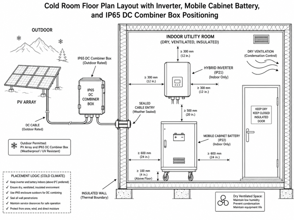
Proper physical deployment of off-grid hardware is critical for long-term reliability in sub-zero regions. Equipment enclosure ratings define whether components require protected indoor installation or can be deployed in outdoor environments.
5.1 Indoor vs. Outdoor Deployment Boundaries
- Inverters & LiFePO4 Batteries (IP21 / IP22 Ratings): Haven Deer hybrid inverters (ALL 486000 Pro / ALL 4812000 Pro) and wall-mounted batteries (AL-WM512100 / AL-WM512200) use IP21 enclosures, while floor-standing mobile cabinet batteries (MB512300 / MB512346) use IP22 enclosures. These components must be installed indoors in a dry, ventilated equipment room or insulated utility space. Direct exposure to rain, snow, or outdoor condensation conditions can create moisture-related reliability risks.
- DC Array Protection (IP65 Rating): The Haven Deer IP65 PV Combiner Box is designed for outdoor PV array environments. Integrating DC surge protection devices (SPD), DC circuit breakers, and string protection components, it consolidates multiple PV inputs before the DC cables enter the building and connect to the inverter. Learn more about Why Off-Grid Solar Kits Require IP65 PV Combiner Boxes.
| Equipment Component | Model Series | IP Rating | Recommended Installation Location | Ambient Temp Limits |
|---|---|---|---|---|
| 6kW / 12kW Hybrid Inverters | ALL 486000 Pro / ALL 4812000 Pro | IP21 | Indoor Utility Room / Dry Garage | -10°C to 50°C |
| Wall-Mounted LFP Batteries | AL-WM512100 / AL-WM512200 | IP21 | Insulated Indoor Wall (Reinforced) | Charge: 0°C to 50°C Discharge: -15°C to 50°C |
| Mobile Cabinet Batteries | MB512300 / MB512346 | IP22 | Insulated Indoor Floor (Verify Load) | Charge: 0°C to 55°C Discharge: -20°C to 55°C |
| PV Array Combiner Box | Haven Deer IP65 Combiner | IP65 | Outdoor Wall / PV Mounting Structure | -25°C to 60°C |
5.2 Condensation Management Strategy
When cold outdoor air enters warm electrical equipment areas, temperature differences can cause moisture condensation on electronic components and circuit boards. To reduce condensation risks:
- Maintain separation between damp living areas and electrical equipment rooms to reduce moisture migration.
- Keep inverter and battery installation areas dry and properly ventilated.
- Ensure battery cabinets remain elevated above concrete floors using heavy-duty casters or insulated wall mounts to reduce conductive heat transfer from cold surfaces.
6. Engineering Checklist: Winterizing Off-Grid Solar ESS Installations
Before the winter season begins, field installers and EPC contractors should complete the following commissioning checklist to verify that off-grid solar ESS installations are prepared for freezing conditions:
- Verify Voc Voltage Margins: Recalculate PV string open-circuit voltage using the site’s historical minimum temperature. Confirm the maximum array Voc remains below the inverter’s 500V DC maximum PV input limit.
- Inspect BMS Communication Protocols: Confirm closed-loop CAN or RS485 communication between the Master BMS and hybrid inverter to verify that battery temperature data and 0°C charging protection logic are correctly transmitted.
- Test Dry Contact Signal Continuity: Activate the inverter dry contact relay through the configuration settings and verify that the connected auxiliary generator receives correct start and stop signals.
- Calibrate Low-Voltage & SOC Triggers: Configure generator start thresholds according to winter operating requirements, typically using 25%–30% SOC to maintain battery reserve during extended low-irradiance periods.
- Inspect Outdoor IP65 Combiner Boxes: Verify DC surge protection device (SPD) indicators, inspect cable gland tightness, and confirm enclosure sealing integrity before winter operation.
- Evaluate Battery Room Insulation: Verify that the battery installation area maintains suitable temperatures, ideally above 5°C, to support normal battery charging performance during winter solar generation periods. For a complete field verification process, see our Commissioning Checklist for Installers.
7. Frequently Asked Questions
Can Haven Deer LiFePO4 batteries be charged in sub-zero temperatures?
No. The integrated BMS automatically enforces a 0°C charging cutoff to prevent lithium plating during low-temperature charging. Discharge operation remains available down to -15°C for wall-mounted models and -20°C for floor-standing mobile cabinet batteries within their specified operating ranges.
Why does photovoltaic open-circuit voltage (Voc) increase during winter?
Solar modules have a negative temperature coefficient of voltage. As cell temperatures decrease, the module open-circuit voltage (Voc) increases, which can raise PV string voltage during cold-weather operation.
What happens if PV array open-circuit voltage exceeds 500V DC in cold weather?
Exceeding the inverter’s 500V DC maximum PV input voltage limit can trigger overvoltage protection and create a risk of MPPT hardware damage. PV arrays must be sized using the site’s historical minimum temperature conditions.
How does the hybrid inverter handle winter solar shortages in remote locations?
The ALL 486000 Pro and ALL 4812000 Pro inverters feature built-in passive dry contact relays. When battery SOC or voltage reaches configured winter thresholds, the inverter sends an automatic start signal to a compatible backup generator to support system operation and battery charging.
Are IP21 or IP22 rated battery storage cabinets safe for unheated outdoor placement?
No. IP21 wall-mounted batteries and IP22 mobile cabinet batteries are designed for indoor, dry installation environments. They should be installed inside an insulated equipment room to prevent condensation and moisture-related damage.
What is the difference between IP21, IP22, and IP65 in an off-grid system?
IP21 and IP22 ratings provide protection against limited water ingress and solid object access for indoor equipment environments according to IEC 60529 Ingress Protection (IP) Ratings. IP65 provides dust-tight protection and resistance against water jets, making it suitable for outdoor PV combiner box installation.
Does cold weather cause permanent damage to LiFePO4 energy storage capacity?
Cold ambient temperatures can temporarily reduce available battery capacity due to increased internal resistance and slower electrochemical reactions. When cell temperatures return to the normal operating range and low-temperature charging protection is maintained, the available capacity can recover.
Can a generator charge the battery bank while simultaneously powering household loads?
Yes. When the generator supplies power through the inverter’s shared AC input terminal, the EMS can provide power to connected AC loads while the internal AC charger recharges the LiFePO4 battery bank according to configured charging parameters.
How many 610W solar panels can be safely wired in series to a 12kW Dual MPPT inverter in freezing climates?
In regions reaching -25°C ambient temperatures, PV string lengths should typically be limited to 8 panels in series per MPPT tracker, producing approximately 443V DC at -25°C and maintaining a safety margin below the inverter’s 500V DC maximum input limit.
Why are Grade A prismatic LiFePO4 cells essential for off-grid winter installations?
Grade A prismatic cells provide consistent manufacturing quality, lower internal resistance, and stable electrochemical performance. These characteristics support improved cell balance across 16S battery configurations during high-current winter operation.
8. Planning an Off-Grid Microgrid in a Cold Climate?
Ensure your off-grid energy storage system is engineered for reliable sub-zero operation and long-term performance. Contact Haven Deer’s engineering team for system design review, cold-weather Voc calculation verification, and customized ESS solutions based on your site conditions.
Contact Us for a Customized Solution