Quick Answer: Grade A LiFePO4 batteries can safely discharge within manufacturer-defined operating limits, reaching -15°C for Haven Deer wall-mounted battery series and -20°C for Haven Deer floor-standing mobile cabinet battery series. However, sub-zero temperatures increase electrolyte viscosity and internal resistance (Ri), causing higher voltage sag under load and reducing available discharge energy to approximately 60%–70% of nominal capacity depending on discharge conditions. System engineers should consider inverter low-voltage cutoff settings, discharge current limits, and temperature derating factors during off-grid solar energy storage system (ESS) design to reduce unexpected low-voltage shutdowns during winter load peaks.
1. Electrochemistry of Low-Temperature LiFePO4 Discharge
Operating lithium iron phosphate (LiFePO4) energy storage batteries in sub-zero environments introduces distinct electrochemical challenges. While charging limitations are primarily associated with lithium plating risks, low-temperature discharge mainly affects ion transport kinetics, internal resistance, voltage stability, and available energy output in cold-climate off-grid installations.
1.1 Electrolyte Viscosity and Lithium-Ion Mobility
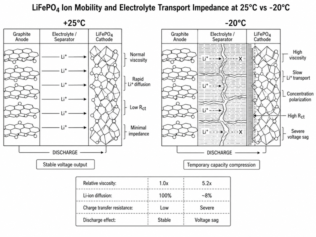
The non-aqueous organic carbonate electrolytes utilized in Grade A LiFePO4 prismatic cells undergo a significant increase in dynamic viscosity as ambient temperatures descend below 0°C. This physical thickening restricts lithium-ion diffusion through the electrolyte matrix.
[25°C Ambient]   Electrolyte Viscosity: Normal   ---> Rapid Li+ Diffusion    ---> Minimal Impedance
[0°C Ambient]    Electrolyte Viscosity: Elevated ---> Slowed Li+ Transport   ---> Moderate Voltage Drop
[-20°C Ambient]  Electrolyte Viscosity: High     ---> High Transport Barrier ---> Severe Voltage Sag
As ambient conditions approach -15°C or -20°C, lithium-ion transport becomes significantly slower due to increased electrolyte viscosity and reduced diffusion kinetics. This ionic slowdown increases concentration polarization within the electrode structures and electrolyte interface, limiting the rate at which lithium ions can move between the graphite anode and LiFePO4 cathode.
Consequently, during discharge, lithium ions experience increased transport resistance through the electrolyte, causing higher polarization losses and a reduction in the operational cell voltage under load.
1.2 Charge Transfer Resistance (Rct) at the Cathode Interface
Beyond electrolyte transport limitations, sub-zero conditions significantly increase charge transfer resistance (Rct) at the electrode interfaces and within the Solid Electrolyte Interphase (SEI) layer. Lower temperatures slow the interfacial reaction kinetics required for lithium ions to migrate and participate in the electrode reaction process.
| Electrochemical Parameter | +25°C (Baseline) | 0°C (Cold Condition) | -10°C (Sub-Zero Condition) | -20°C (Extreme Cold Condition) |
|---|---|---|---|---|
| Relative Electrolyte Viscosity | 1.0× | Increased | Higher | Significantly Increased |
| Li-Ion Diffusion Rate | 100% Baseline | Reduced | Further Reduced | Severely Reduced |
| Charge Transfer Resistance (Rct) | Baseline | Increased | High | Significantly High |
Importantly, discharging a 16S nominal 51.2V LiFePO4 battery pack within the specified low-temperature operating range does not cause lithium plating or permanent electrode damage. Lithium plating is primarily associated with charging LiFePO4 cells below 0°C, where lithium ions cannot efficiently intercalate into the graphite anode structure. During discharge, lithium ions move out of the graphite anode structure naturally, while increased internal resistance temporarily reduces voltage performance.
The primary engineering impact during sub-zero discharge is temporary performance reduction, including increased voltage sag, lower available discharge energy, and reduced power output capability under high current demand.
2. Voltage Sag Mechanics, Internal Resistance (Ri), and C-Rate Limits
Understanding the interaction between internal resistance (Ri), discharge current demand (I), and terminal voltage (V_terminal) is critical for designing reliable cold-climate off-grid energy storage systems and preventing unexpected inverter shutdowns during winter operation.
2.1 Quantifying Internal Resistance Increase in Sub-Zero States
The overall DC internal resistance (Ri) of a prismatic LiFePO4 cell consists of electronic resistance from conductive components, electrolyte resistance, and interfacial charge transfer impedance. While electronic resistance remains relatively stable across temperature ranges, electrolyte and charge transfer resistance increase significantly as temperatures decrease.
The temperature-dependent change in internal resistance can be represented using an engineering estimation model:
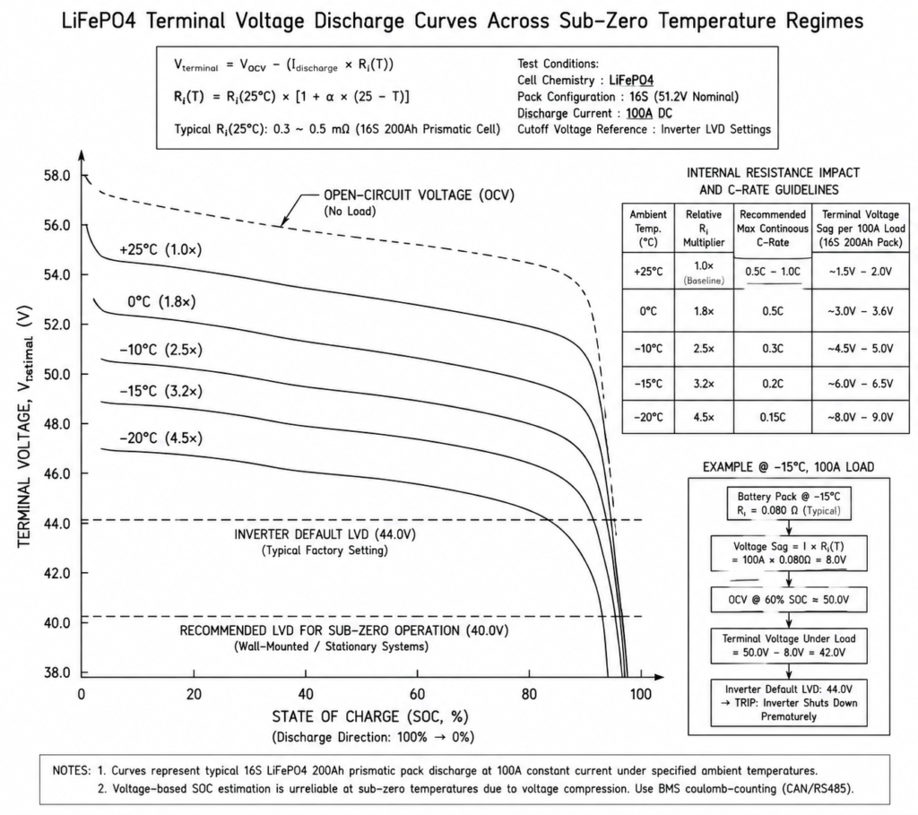
Ri(T)=Ri(25°C)×[1+α×(25−T)]
Where:
- Ri(T) = Internal resistance at target operating temperature T (°C)
- Ri(25°C) = Baseline internal resistance measured under standard test conditions for the specific LiFePO4 cell design
- α = Temperature coefficient representing the increase trend of internal resistance under low-temperature conditions
- T = Operating cell temperature (°C)
Applying Ohm’s Law, the actual terminal voltage supplied to the hybrid inverter during discharge is expressed as:
V_terminal=V_OCV−(I_discharge×Ri(T))
Where:
- V_terminal = Real-time battery terminal voltage under load (V)
- V_OCV = Open-circuit voltage reflecting the battery State of Charge (V)
- I_discharge = Discharge current demand (A)
- Ri(T) = Temperature-adjusted internal resistance (Ω)
At -15°C, internal resistance can increase several times compared with the 25°C baseline value, depending on cell chemistry, construction, and operating conditions. If a heavy inductive load such as a water pump or motor compressor requires high startup current, the voltage drop caused by I_discharge × Ri(T) increases significantly, causing the battery terminal voltage to temporarily fall below the expected operating voltage.
2.2 Low-Voltage Cutoff (40.0V / 44.0V) Trigger Risks Under Peak Loads
A common cold-weather operating issue occurs when an off-grid hybrid inverter triggers a low-voltage shutdown even though the battery monitoring system indicates remaining SOC is available, highlighting the importance of BMS protection layers including voltage, current, and thermal safeguards.
[Inverter Load Demand: High Current]
                │
                ▼
[Battery Pack at Low Temperature] ──► Voltage Sag = Discharge Current × Ri(T)
                │
                ▼
[Available Battery Voltage] - [Voltage Sag] = Reduced Terminal Voltage
                │
                ▼
[Inverter Low-Voltage Protection Threshold] ──► Possible Shutdown
Many 48V hybrid inverters use configurable low-voltage protection thresholds, commonly set within the 44.0V to 46.0V range depending on manufacturer specifications and system design requirements.
At 25°C, a 16S LFP pack approaching 44.0V (approximately 2.75V per cell) generally indicates a deeply discharged condition near the lower SOC range. However, at -15°C, increased internal resistance can cause significant temporary voltage sag under load, potentially reducing terminal voltage below the inverter protection threshold even when usable battery energy remains.
Engineering Tip: When commissioning 51.2V LiFePO4 battery systems in cold climates, configure inverter low-voltage protection parameters according to the battery manufacturer’s recommended limits and ensure closed-loop BMS communication is active. For sub-zero operation, limiting discharge current to approximately 0.2C to 0.3C helps reduce I × Ri(T) voltage drop and minimizes unexpected inverter shutdowns caused by temporary voltage sag.
Common Mistake: Relying only on 25°C open-circuit voltage tables or voltage-based SOC estimation during sub-zero operation can create inaccurate battery status readings. Cold-temperature voltage compression requires system control to prioritize closed-loop BMS SOC data transmitted through CAN or RS485 communication protocols.
| Ambient Temperature (°C) | Relative Internal Resistance Trend | Recommended Maximum Continuous Discharge C-Rate | Expected Voltage Sag Trend |
|---|---|---|---|
| +25°C | Baseline | 0.5C – 1.0C | Low voltage sag |
| 0°C | Increased | ≤0.5C | Moderate voltage sag |
| -10°C | Significantly Increased | ≤0.3C | Higher voltage sag |
| -15°C | High Increase | ≤0.2C | Severe voltage sag |
| -20°C | Very High Increase | ≤0.15C | Extreme voltage sag |
3. Hardware Operational Limits: Wall-Mounted vs. Floor-Standing Cabinet Batteries
Different battery form factors exhibit different thermal behaviors and operational limits under sub-zero conditions. Enclosure design, protection rating, thermal mass, and cell arrangement influence low-temperature discharge performance and system reliability.
3.1 Wall-Mounted Series (AL-WM512100 / AL-WM512200) Performance at -15°C
Wall-mounted batteries, such as the Haven Deer AL-WM512100 (5.12kWh / 100Ah) and AL-WM512200 (10.24kWh / 200Ah) models, feature IP21 enclosures designed for indoor residential and light commercial energy storage installations.
- Operating Discharge Window: -15°C to 50°C
- Operating Charge Window: 0°C to 50°C
- Thermal Behavior: The compact wall-mounted enclosure has lower thermal mass compared with cabinet-based batteries. When installed in unheated spaces, the battery temperature can follow ambient temperature changes more quickly during extended cold periods.
- Discharge Boundary: At -15°C, the BMS allows discharge operation within the rated current limits (100A for AL-WM512100 and 200A for AL-WM512200). System designers should account for reduced available energy caused by increased internal resistance and lower operating voltage during cold discharge. When cell temperature falls below the specified discharge limit, the BMS activates low-temperature protection and disconnects the battery output.
3.2 Mobile Cabinet Series (MB512300 / MB512346) Extended Range down to -20°C
For larger residential, agricultural, commercial, and off-grid applications requiring higher energy capacity, Haven Deer Floor-standing Mobile Cabinet Batteries, including the MB512300 (15.0kWh) and MB512346 (18.0kWh), provide extended low-temperature discharge capability.
- Operating Discharge Window: -20°C to 55°C
- Operating Charge Window: 0°C to 55°C
- Thermal Advantage: Built with IP22 floor-standing mobile cabinet enclosures and high-capacity prismatic cells (300Ah / 346Ah), these batteries provide higher thermal mass than compact wall-mounted units. The larger enclosure reduces rapid temperature changes during cold-weather operation.
- Extended Sub-Zero Boundary: The integrated BMS architecture in the MB series supports discharge operation down to -20°C within the specified operating range. During discharge, internal resistance losses generate limited heat that can help stabilize cell temperature during extended operation.
[AL-WM Wall-Mounted Series]        ---> IP21 Indoor Enclosure ---> Lower Thermal Mass  ---> Discharging Down to -15°C
[MB Floor-Standing Mobile Cabinet] ---> IP22 Cabinet Enclosure ---> Higher Thermal Mass ---> Discharging Down to -20°C
| Specification Parameter | AL-WM512100 | AL-WM512200 | MB512300 | MB512346 |
|---|---|---|---|---|
| Form Factor | Wall-Mounted | Wall-Mounted | Floor-standing Mobile Cabinet | Floor-standing Mobile Cabinet |
| Nominal Energy (kWh) | 5.12 kWh | 10.24 kWh | 15.0 kWh | 18.0 kWh |
| Nominal Voltage / Capacity | 51.2V / 100Ah (102Ah Cell Class) | 51.2V / 200Ah (206Ah Cell Class) | 51.2V / 300Ah | 51.2V / 346Ah |
| Discharge Temp Limits | -15°C to 50°C | -15°C to 50°C | -20°C to 55°C | -20°C to 55°C |
| Charge Temp Limits | 0°C to 50°C | 0°C to 50°C | 0°C to 55°C | 0°C to 55°C |
| Protection Rating | IP21 | IP21 | IP22 | IP22 |
| Continuous Discharge Current | 100A | 200A | 200A | 200A |
4. Sizing Battery Autonomy for Sub-Zero Usable Capacity Degradation
When engineering an off-grid solar energy storage kit for cold climates such as Eastern Europe, Central Asia, or high-altitude regions, sizing calculations based only on 25°C nominal battery ratings may underestimate winter energy requirements and reduce system autonomy.
4.1 Derating Factor Math Model (η_T)
To ensure the battery system meets daily energy requirements during extreme cold periods, system designers should introduce a Temperature Derating Factor (η_T) together with Depth of Discharge (DoD), cable loss variables, and accurate daily household consumption and battery autonomy calculations.
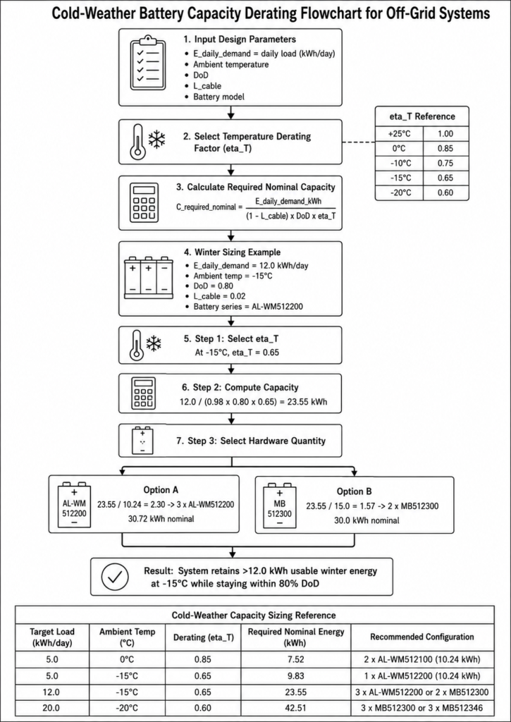
The total nominal battery capacity (C_required_nominal) is calculated using the following engineering formula:
C_required_nominal=(1−L_cable)×DoD×η_T×E_daily_demand_kWh
Where:
- C_required_nominal = Total required nominal battery bank capacity (kWh)
- E_daily_demand_kWh = Daily electrical consumption of connected loads (kWh/day)
- L_cable = DC cable and connection loss factor (typically 0.02 to 0.03 for 2%–3% loss)
- DoD = Recommended Depth of Discharge allowance (0.80 represents an 80% usable energy window commonly applied for long-cycle-life system design)
- η_T = Temperature Capacity Derating Efficiency Factor
Temperature Derating Factor (η_T) Reference:
- η_T at +25°C: 1.00 (100% nominal usable energy)
- η_T at 0°C: 0.85 (85% available energy)
- η_T at -10°C: 0.75 (75% available energy)
- η_T at -15°C: 0.65 (approximately 65% available energy under the defined design conditions)
- η_T at -20°C: 0.60 (approximately 60% available energy under the defined design conditions for Mobile Cabinet Series applications)
4.2 Step-by-Step Sizing Example for Eastern Europe Winter Loads
Consider a residential off-grid villa project in Eastern Europe with the following winter design parameters:
- Daily Essential Winter Load (E_daily_demand): 12.0 kWh/day
- Design Ambient Temperature: -15°C
- Target Depth of Discharge (DoD): 80% (0.80)
- Estimated DC Cable Loss (L_cable): 2% (0.02)
- Target Battery Series: Haven Deer AL-WM512200 (10.24kWh nominal capacity per module)
Step 1: Select the Temperature Derating Factor
At the -15°C design condition, the selected temperature derating factor is η_T = 0.65.
Step 2: Calculate Required Nominal Capacity
C_required_nominal=(1−0.02)×0.80×0.6512.0 kWh=0.98×0.80×0.6512.0=0.509612.0=23.55 kWh
Step 3: Hardware Quantity Selection
- Option A (10.24kWh Modules): 23.55 kWh ÷ 10.24 kWh ≈ 2.30 units, therefore rounded up to 3 units of AL-WM512200, with a total nominal capacity of 30.72 kWh
- Option B (15.0kWh Cabinet Modules): 23.55 kWh ÷ 15.0 kWh ≈ 1.57 units, therefore rounded up to 2 units of MB512300, with a total nominal capacity of 30.0 kWh
By specifying three 10.24kWh wall-mounted batteries or two 15.0kWh floor-standing mobile cabinet batteries, the system provides sufficient nominal capacity to maintain the required winter energy availability while maintaining the target DoD limit and reducing voltage sag risk during peak loads.
| Target Load (kWh/day) | Ambient Temp (°C) | Derating (\eta_T) | Required Nominal Energy (kWh) | Recommended Haven Deer Configuration |
|---|---|---|---|---|
| 5.0 kWh | 0°C | 0.85 | 7.52 kWh | 2 × AL-WM512100 (10.24 kWh Nominal Capacity) |
| 5.0 kWh | -15°C | 0.65 | 9.83 kWh | 1 × AL-WM512200 (10.24 kWh Nominal Capacity) |
| 12.0 kWh | -15°C | 0.65 | 23.55 kWh | 3 × AL-WM512200 (30.72 kWh Nominal Capacity) or 2 × MB512300 (30.0 kWh Nominal Capacity) |
| 20.0 kWh | -20°C | 0.60 | 42.51 kWh | 3 × MB512300 (45.0 kWh Nominal Capacity) or 3 × MB512346 (54.0 kWh Nominal Capacity) |
5. BMS Protection Logic and Thermal Safeguards
The Battery Management System (BMS) integrated within Haven Deer energy storage modules acts as the primary battery protection controller, executing layered safety logic to manage temperature, current, voltage, and communication-based protection requirements.
5.1 Discharge Overcurrent & Under-Temperature Interlocks
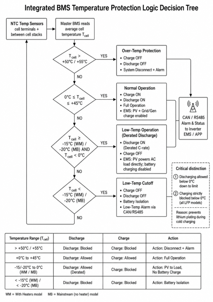
The master BMS continuously monitors internal NTC (Negative Temperature Coefficient) thermistors installed near prismatic cell groups to measure real-time cell temperature conditions.
If cell temperature drops below the specified low-temperature discharge threshold (-15°C for AL-WM wall-mounted units and -20°C for MB floor-standing mobile cabinet units), the BMS disables battery discharge output and transmits a low-temperature protection status signal to the hybrid inverter through CAN or RS485 communication.
[NTC Temperature Sensors] ---> Measure Cell Temperature T_cell
                                              │
                             ┌────────────────┴────────────────┐
                             ▼                                 ▼
              [T_cell Within Operating Range]   [T_cell Below Discharge Limit]
                             │                                 │
                             ▼                                 ▼
                      Discharge Enabled               BMS Blocks Discharge
                 (Apply Temperature-Based     (Send Temperature Protection Alarm)
                      Current Limits)
5.2 Critical Engineering Distinction: Discharge Permitted vs. Charge Cutoff (0°C)
A common operational misunderstanding is the difference between low-temperature discharge operation and low-temperature charging protection.
Low-Temperature Thermal Interlocks:
├── Discharging: Allowed within rated limits down to -15°C (AL-WM) / -20°C (MB)
└── Charging:    Blocked below 0°C without active heating support (All LFP Models)
- Discharging Allowed (<0°C down to limits): During discharge, lithium ions naturally move from the graphite anode toward the cathode. Increased internal resistance causes temporary voltage reduction and lower power capability, but does not create lithium plating.
- Low-Temperature Charge Cutoff (<0°C): Applying charge current to an LFP cell below 0°C can cause lithium ions to deposit on the graphite anode surface instead of properly intercalating into the electrode structure. This lithium plating can permanently reduce capacity and increase internal short-circuit risk.
Common Mistake: Attempting to charge cold LFP batteries by manually bypassing BMS low-temperature protection through inverter settings. Charging below 0°C without an appropriate heating strategy can permanently degrade battery cells and may affect warranty coverage.
| Cell Temperature Zone | BMS Discharge Status | BMS Charge Status | Closed-Loop Inverter EMS Action |
|---|---|---|---|
| Above +50°C / +55°C | Blocked (Over-Temperature Protection) | Blocked (Over-Temperature Protection) | System Alarm and Protection Shutdown |
| 0°C to +45°C | Allowed (Normal Operation) | Allowed (Normal Operation) | Full System Operation (PV + Grid/Generator Charging) |
| Below 0°C to Discharge Limit | Allowed (Temperature-Derated Current Limit) | Blocked (Low-Temperature Charge Cutoff) | PV Can Supply Loads Directly; Battery Charging Disabled |
| Below -15°C (AL-WM) / Below -20°C (MB) | Blocked (Discharge Protection) | Blocked (Charge Protection) | Battery Output Isolation and Protection Alarm |
6. Field Engineering and Cold-Environment Installation Standards
Achieving reliable long-term operation in freezing regional climates requires combining appropriate BMS protection logic with correct thermal management, field installation practices, and a complete understanding of off-grid solar ESS performance in sub-zero climates.
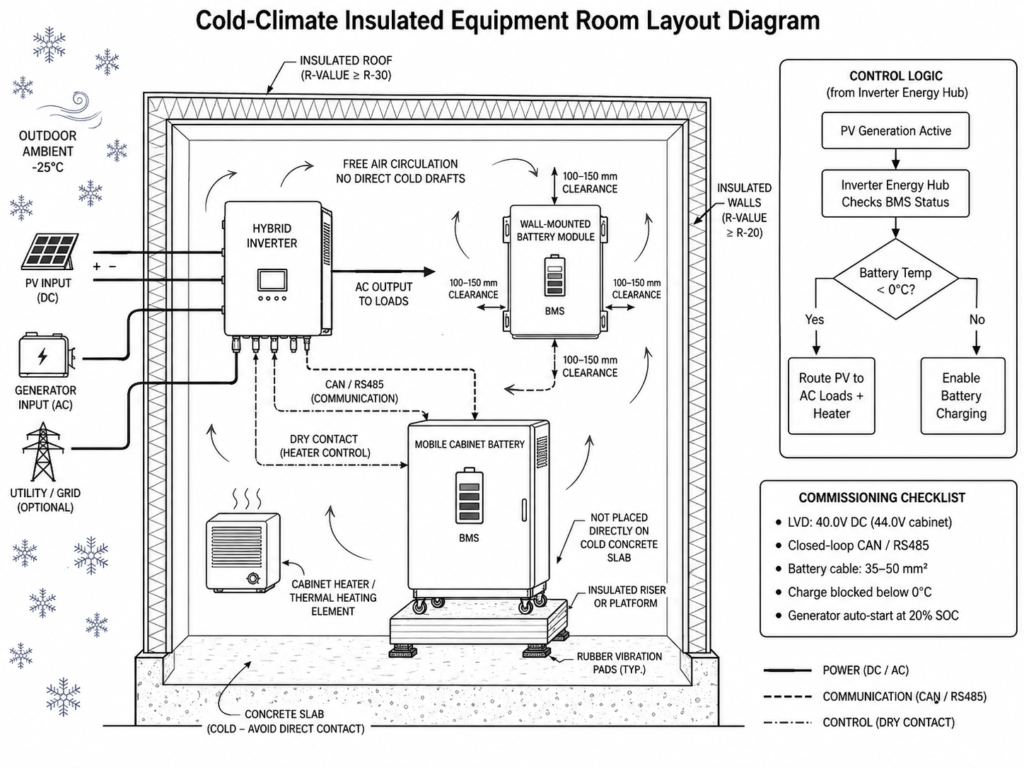
6.1 Thermal Insulation Enclosures and Equipment Room Design
Installing battery banks directly outdoors or in uninsulated structures exposed to sub-zero temperatures can reduce discharge performance and increase the probability of low-temperature charge blocking during winter operation.
- Dedicated Equipment Rooms: Install batteries inside an insulated utility room, basement, or properly designed thermal enclosure.
- Ground Elevation: Avoid placing floor-standing mobile cabinet batteries directly on uninsulated concrete slabs in freezing environments. Concrete can accelerate heat transfer away from the enclosure. Install units on suitable insulated bases, vibration pads, or equipment risers to reduce thermal loss.
- Air Circulation Space: Maintain sufficient clearance around wall-mounted batteries and floor-standing cabinets to support uniform air circulation while preventing direct exposure to cold drafts from external openings.
6.2 Pre-Heating Strategies and Inverter/BMS Integration
To transition a battery bank from cold discharge conditions into charging operation during winter mornings, thermal management strategies should be incorporated into the system design.
               [PV Generation Active in Winter]
                              │
                              ▼
        [Hybrid Inverter Energy Hub Checks BMS Status]
                              │
                              ├─► Battery Temp < 0°C? ──► Supplies PV Power to Loads and Enables Heating Strategy
                              │
                              └─► Battery Temp ≥ 0°C? ──► Enables Battery Charging Current
- Self-Heating During Discharge: Operating essential loads draws current from the battery bank and generates internal resistance losses ( I²R). This heat generation may gradually increase cell temperature during operation, but should not be considered a replacement for dedicated thermal management.
- Dry Contact Auxiliary Heating Integration: Haven Deer hybrid inverters (ALL 486000 Pro / ALL 4812000 Pro) feature programmable passive Dry Contact relay outputs. System engineers can integrate external heating devices through these dry contacts to support battery temperature management when cell temperatures approach low-temperature charging limits.
Sub-Zero Commissioning & Site Preparation Checklist:
- Verify Inverter Low-Voltage Protection Settings: Configure DC low-voltage protection parameters according to battery manufacturer recommendations and account for additional voltage sag during cold-weather operation.
- Confirm Communication Interface: Verify closed-loop CAN or RS485 communication between the Master BMS and hybrid inverter Energy Hub before commissioning.
- Inspect Cable Sizing: Ensure DC battery cables are correctly sized according to system current requirements and installation distance to minimize additional external voltage drop.
- Verify Minimum Charge Temperature Interlock: Confirm that the system displays charge protection status when cell temperature sensors detect conditions below 0°C while discharge operation remains available.
- Set Generator Dry Contact Auto-Start Thresholds: Configure hybrid inverter dry contact auto-start logic based on BMS SOC thresholds to activate generator backup during prolonged low-solar periods and maintain continuous critical load supply.
7. Frequently Asked Questions
Q1: Can LiFePO4 batteries be damaged by discharging them at -20°C?
Discharging within manufacturer-defined operating limits, such as the Haven Deer MB floor-standing mobile cabinet series rated to -20°C, does not cause permanent cell damage when discharge current is controlled and battery voltage remains within the BMS protection range.
Q2: Why does my off-grid inverter trigger a low-battery voltage alarm at -10°C when SOC is above 50%?
Low ambient temperatures increase cell internal resistance (Ri), causing temporary voltage sag under load current (V_sag = I × Ri). This voltage reduction can pull the battery terminal voltage below the inverter low-voltage protection threshold, triggering a shutdown even when remaining battery energy is still available.
Q3: What is the difference between sub-zero discharging and sub-zero charging for LFP cells?
During discharge, lithium ions naturally move from the graphite anode toward the cathode, while increased internal resistance reduces voltage performance. Charging below 0°C can cause lithium ions to deposit on the graphite anode surface instead of properly intercalating into the electrode structure, creating lithium plating risks and potential permanent capacity loss.
Q4: How much usable capacity is lost at -15°C?
At -15°C ambient conditions, available discharge energy can decrease by approximately 30% to 35% compared with standard 25°C ratings due to increased internal resistance, voltage sag, and reduced discharge efficiency.
Q5: Should I insulate my indoor battery cabinet in cold climates?
Yes. Installing battery banks inside an insulated equipment room or thermal enclosure reduces rapid heat loss and helps maintain more stable cell temperatures during cold-weather operation.
Q6: What happens if solar power becomes available while the battery is at -10°C?
The Haven Deer BMS allows the hybrid inverter to use available solar PV power for connected AC loads while preventing battery charging when cell temperatures remain below 0°C. Battery charging resumes after cell temperatures return to the permitted charging range.
Q7: What is the recommended maximum continuous discharge current for a 200Ah LFP battery at -15°C?
For a 200Ah LFP battery operating at -15°C, limiting continuous discharge current to approximately 0.2C (40A) can reduce voltage sag and lower the risk of inverter low-voltage protection events.
Q8: Can dry contacts on Haven Deer inverters trigger external heating pads?
Yes. Haven Deer hybrid inverters feature programmable passive dry contact terminals that can control external heating devices according to configured system conditions, including battery temperature signals from the BMS.
Q9: Does cold weather permanently degrade LiFePO4 battery cycle life?
Sub-zero discharge within manufacturer-defined operating limits does not permanently reduce LiFePO4 cycle life. Available capacity typically returns as cell temperature recovers to normal operating conditions.
Q10: Are Haven Deer MB series batteries suitable for outdoor cold-climate installation?
Haven Deer MB series batteries carry an IP22 protection rating and are designed for indoor, sheltered, or enclosed equipment rooms. They should not be installed in locations directly exposed to rain, snow, or uncontrolled outdoor weather conditions.
Q11: What standard governs industrial low-temperature LFP safety?
IEC 62619 defines safety requirements for industrial lithium battery systems, including requirements related to battery protection functions and safe operating conditions.
Q12: How do I calculate total system battery capacity needed for winter autonomy?
Calculate required winter battery capacity by dividing daily energy demand (kWh) by the combined factors of cable efficiency, target Depth of Discharge (0.80), and the temperature derating factor (η_T = 0.65 at -15°C). The resulting nominal capacity should be selected based on the expected cold-weather operating conditions.
8. Planning an Off-Grid System in a Cold Climate Environment?
Get a Complete Cold-Climate Solar ESS System Sizing and Thermal Engineering Review from Haven Deer Engineers.
Sub-zero winter conditions require accurate battery sizing, discharge current planning, and inverter protection settings to maintain reliable off-grid system operation. Haven Deer provides integrated Solar ESS Kits with matched battery, BMS, and hybrid inverter solutions designed for cold-climate off-grid applications in Eastern Europe and other low-temperature regions.
What Our Engineering Review Includes:
- Customized Winter Autonomy Analysis and Battery Capacity Sizing Calculations
- Single-Line Diagram (SLD) and System Architecture Review
- Hybrid Inverter and BMS Parameter Configuration Review
- OEM / ODM Enclosure Design and Thermal Management Options for Distributors and EPC Contractors
Contact Haven Deer Engineers for a Customized Cold-Climate Solar ESS Solution