Quick Answer: A floor-standing solar battery packages high-capacity LiFePO4 storage into a heavy-duty, IP22-rated enclosure on reinforced casters. These 51.2V off-grid solar battery units hold 15.0kWh (300Ah) or 18.0kWh (346Ah) and sustain a 200A continuous discharge. The onboard BMS handles standard CAN/RS485/RS232 protocols and supports master-slave paralleling. This simplifies capacity scaling.
1. Structural Engineering & Floor Load Dynamics of Floor-Standing Solar Battery
1.1 Mass Distribution and Floor Loading Calculations (129kg to 163kg)
Unlike wall-mounted modules that anchor to structural studs, floor-standing battery cabinets transfer their entire dead load directly to the slab. Concentrating high mass into a small footprint makes floor-load calculations mandatory. The Haven Deer MB512300 (15.0kWh) weighs 129kg, while the MB512346 (18.0kWh) weighs 163kg. Field crews must verify slab capacity prior to delivery and rigging.
Calculate static floor pressure using the cabinet base contact area:
P_floor = (m × g) / A_footprint
Where:
- P_floor: Static floor loading pressure in Pascals (Pa) or Kilopascals (kPa).
- m: Total cabinet mass in kilograms (kg).
- g: Gravitational acceleration constant (9.81m/s²).
- A_footprint: Base contact footprint area of the cabinet enclosure in square meters (m²).
For an MB512346 (163kg), the 0.651m × 0.540m base yields a 0.35m² footprint across the caster spread:
P_floor = (163kg × 9.81m/s²) / 0.35m² = 4568.6Pa = 4.57kPa (approx. 466kg/m²)
Most commercial concrete slabs support at least 5.0kPa (500kg/m²). A single MB512346 easily clears this threshold, but paralleled multi-cabinet banks concentrate point loads quickly. Space cabinets strategically to distribute weight across structural slab bays.
| Cabinet Model | Nominal Energy | Pack Weight | Base Footprint (L × W) | Calculated Static Pressure | Standard Floor Compliance |
| MB512300 | 15.0kWh | 129kg | 0.651m × 0.540m (~0.35m²) | 3.61kPa (368kg/m²) | Site verification required |
| MB512346 | 18.0kWh | 163kg | 0.651m × 0.540m (~0.35m²) | 4.57kPa (466kg/m²) | Site verification required |
| 6 × MB512346 Bank | 108.0kWh | 978kg | Array spacing required | Distributed array calculation | Structural layout plan required |
1.2 Heavy-Duty Caster Rating, Vibration Isolation, and Mobility Protocols
Heavy-duty casters streamline transport and servicing without requiring overhead rigging. This eliminates structural wall-anchoring—a major advantage over 100kg+ wall units like the AL-WM512200 (102kg). However, mobile enclosures require strict caster load ratings and positive floor locking.
Reinforced swivel casters fitted with polyurethane treads provide high rollability while protecting epoxy-coated floors. Polyurethane also damps low-amplitude transit vibrations during positioning.
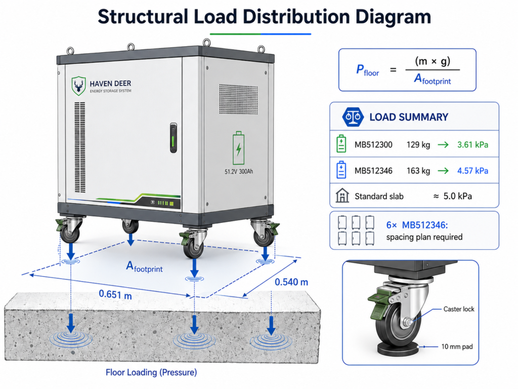
Engineering Tip: Lock all caster brakes immediately once the cabinet reaches its landing position. In high-vibration environments like generator rooms or agricultural processing plants, place 10mm neoprene isolation pads beneath each wheel. This eliminates mechanical creep and isolates internal busbars from cyclic vibration fatigue.
2. Electrochemical Performance: Grade A Prismatic Cells & 51.2V 16S Architecture
2.1 300Ah vs. 346Ah Cell Configuration & Nominal Voltage Bands
Haven Deer mobile cabinets run grade a lifepo4 cells configured in a 16S array. At 3.2V nominal per cell, 16 cells in series establish the standard 51.2V DC bus:
16 × 3.2V = 51.2V DC
The operating window spans 44.0V to 58.4V DC, with a recommended charge setpoint of 56.0V DC. This native 51.2V profile directly matches standard 48V low-voltage hybrid inverters.
| Parameter | MB512300 Cabinet Battery | MB512346 Cabinet Battery |
| Cell Chemistry | Grade A LiFePO4 Prismatic | Grade A LiFePO4 Prismatic |
| Cell Configuration | 16S architecture (300Ah cells) | 16S architecture (346Ah cells) |
| Nominal Voltage | 51.2V DC | 51.2V DC |
| Rated Capacity | 300Ah | 346Ah |
| Total Energy Output | 15.0kWh | 18.0kWh |
| Voltage Operating Window | 44.0V to 58.4V DC | 44.0V to 58.4V DC |
| Continuous Charge Current | 150A | 150A |
| Continuous Discharge Current | 200A | 200A |
| Usable Energy (90% DoD) | 13.5kWh | 16.2kWh |
2.2 Cycle Life Longevity: 6,000 Cycles @ 90% DoD vs. 10,000 Cycles @ 80% DoD
Usable energy throughput depends directly on the programmed Depth of Discharge (DoD). Calculate cumulative lifetime throughput using standard cycle parameters:
E_lifetime = E_nominal × DoD × Cycles × η_roundtrip
Where:
- E_lifetime: Total cumulative energy output delivered across battery life (kWh).
- E_nominal: Rated nominal capacity of the battery pack (kWh).
- DoD: Depth of Discharge operational ratio (e.g., 0.80 or 0.90).
- Cycles: Number of complete charge/discharge cycles achieved at specified DoD.
- η_roundtrip: Round-trip efficiency factor used for lifetime energy estimation.
For an MB512300 (15.0kWh) operated daily at 80% DoD over 10,000 cycles:
E_lifetime = 15.0kWh × 0.80 × 10,000 × 0.95 = 114,000kWh (114MWh)
If the same unit operates at 90% DoD with a cycle life rating of 6,000 cycles:
E_lifetime = 15.0kWh × 0.90 × 6,000 × 0.95 = 76,950kWh (76.95MWh)
Common Mistake: Setting inverter cutoffs to 100% DoD during daily cycling. Routine deep discharges accelerate cathode lattice strain and thicken the solid electrolyte interphase (SEI) layer. Capping daily cycling between 80% and 90% DoD yields significantly higher lifetime MWh. Shallow cycling preserves cell chemistry.
3. High-Current BMS & Master-Slave Parallel Expansion Architecture
3.1 200A Continuous Discharge Handling and Busbar Sizing
The integrated BMS in the MB512300 and MB512346 manages cell telemetry, safety trips, and high-current discharge. Both models sustain 150A continuous charging and 200A continuous discharging. At a nominal operating voltage of 51.2V, a 200A continuous discharge delivers over 10kW of active power:
P_output = 51.2V × 200A = 10,240W (10.24kW)
Sustaining 200A requires heavy copper busbars to limit I²R Joule heating. Low contact resistance prevents localized hot spots under full load.
3.2 DIP Switch Addressing & Multi-Pack Closed-Loop Communication (CAN/RS485)
Paralleling up to six cabinets expands capacity under a coordinated Master-Slave BMS architecture.
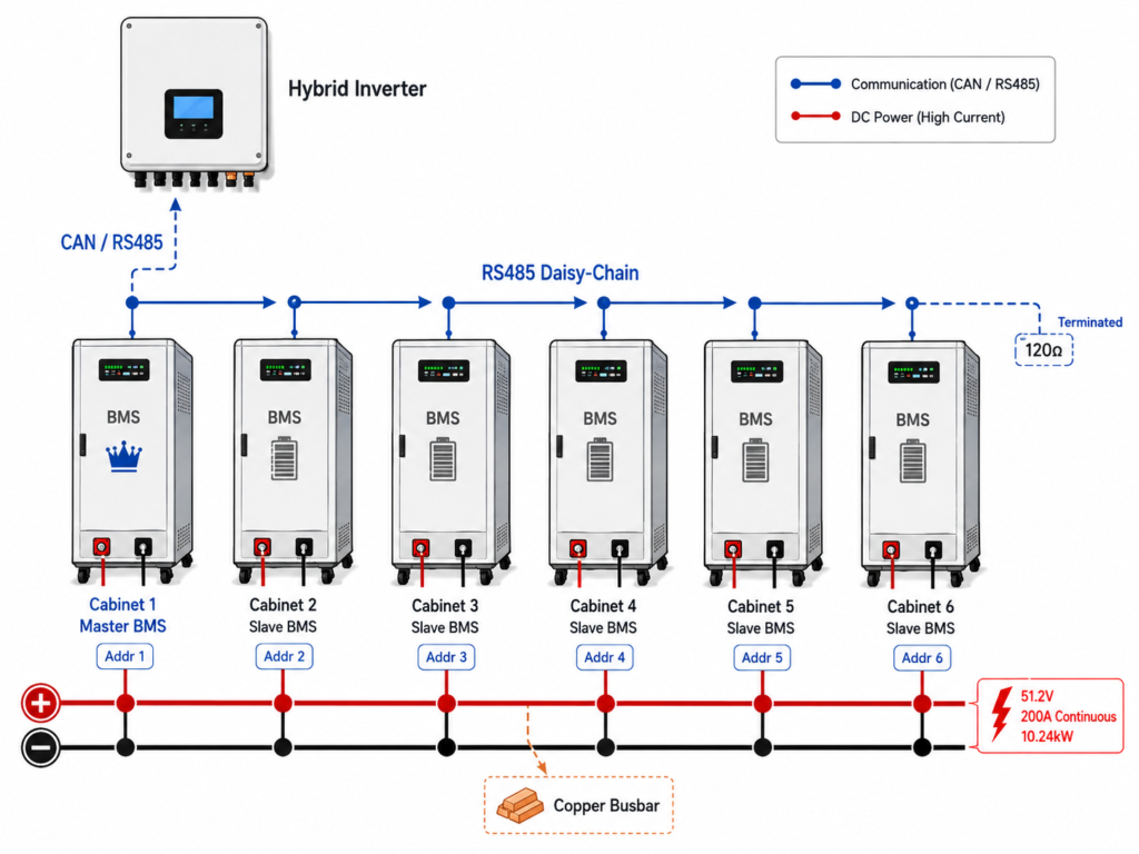
Hardware DIP switches set pack hierarchy: one Master and up to five Slaves. The Master aggregates pack telemetry—SoC, pack voltage, string current, and cell temperatures—then broadcasts unified charge and discharge limits to the hybrid inverter via CAN or RS485.
| Cabinet Position | BMS Role | Address | Communication Connection |
| Cabinet 1 | Master BMS | Address 1 | CAN/RS485 to Inverter + RS485 to Pack 2 |
| Cabinet 2 | Slave 1 | Address 2 | RS485 daisy-chain to Cabinet 3 |
| Cabinet 3 | Slave 2 | Address 3 | RS485 daisy-chain to Cabinet 4 |
| Cabinet 4 | Slave 3 | Address 4 | RS485 daisy-chain to Cabinet 5 |
| Cabinet 5 | Slave 4 | Address 5 | RS485 daisy-chain to Cabinet 6 |
| Cabinet 6 | Slave 5 | Address 6 | RS485 bus termination at final pack |
3.3 Parallel Busbar & Communication Setup Checklist:
- [ ] Verify Voltage Matching: Verify open-circuit pack voltages match within 0.5V DC before landing DC cables to eliminate destructive inrush cross-currents.
- [ ] Set Hardware DIP Addresses: Assign unique binary addresses on the DIP bank with main DC breakers open and control power off.
- [ ] Daisy-Chain Inter-Pack Comms: Daisy-chain shielded RS485 cables sequentially from the Master down through each successive Slave unit.
- [ ] Establish Inverter Comms: Terminate the CAN or RS485 communication link directly from the Master BMS into the hybrid inverter’s dedicated battery port.
- [ ] Install Symmetrical DC Cabling: Route equal-length, identical-gauge conductor pairs from each cabinet to a centralized DC combiner busbar to maintain balanced dynamic current sharing.
4. Thermal Management & Operating Limits (-20°C to 55°C)
4.1 Passive Cabinet Airflow and IP22 Enclosure Thermal Dissipation
The Haven Deer mobile enclosure carries an IP22 rating for indoor utility rooms, preventing finger contact with energized busbars and shedding light overhead condensation.
At 150A charge and 200A discharge rates, thermal management relies entirely on natural convection. Cooler ambient air enters through lower louvered vents, absorbs heat across cell surfaces, and exits through top exhaust slots via thermal buoyancy. Omitting active cooling fans eliminates a frequent mechanical failure point.
4.2 BMS Thermal Protection Boundaries: Charge Cutoff (0°C) vs. Sub-Zero Discharge (-20°C)
LiFePO4 intercalation kinetics diverge sharply between charging and discharging in freezing environments.
| Operational Mode | Permissible Temperature Band | BMS Protection Response |
| Battery Charging | 0°C to 55°C | BMS trips charge path below 0°C and above 55°C |
| Battery Discharging | -20°C to 55°C | BMS trips discharge path below -20°C and above 55°C |
| Storage Temperature | -15°C to 50°C | Maintain 40%–60% SoC in dry, unpowered storage |
Engineering Tip: Never bypass LiFePO4 low temperature charging limits in unconditioned sites. Forcing charge current below 0°C causes metallic lithium plating on the graphite anode, inducing capacity fade and dendrite short risks. The BMS enforces a hard charge cutoff at 0°C while allowing discharge down to -20°C. Cold cells discharge safely, but cannot charge.
5. Multi-Input System Integration: Coordinated Control with Hybrid Inverters & Generators
5.1 Interfacing Cabinet Batteries with Dual MPPT Hybrid Inverters (6kW / 12kW)
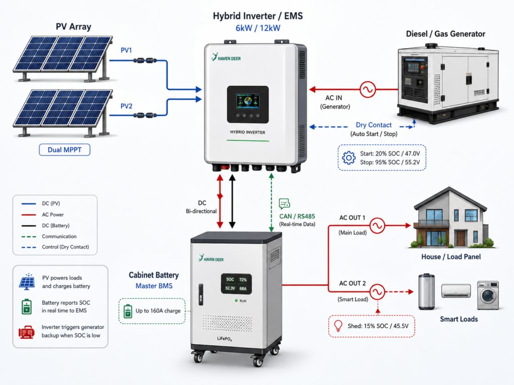
Within an off-grid solar power system architecture, MB-series mobile cabinets integrate directly with Haven Deer hybrid solar inverters, including the ALL 486000 Pro (6kW, single MPPT) and ALL 4812000 Pro (12kW, dual independent MPPT). Closed-loop protocols govern DC power distribution.
The hybrid inverter operates as the core energy controller. Over closed-loop CAN or RS485, its onboard EMS dynamically modulates charge and discharge current limits against real-time telemetry from the Master BMS. In Solar-Priority (SBU) mode, PV generation serves active AC loads first, redirecting surplus array yield to the battery bank at up to 100A on the ALL 486000 Pro and 160A on the ALL 4812000 Pro.
5.2 Dry Contact Generator Auto-Start Threshold Settings based on Cabinet SOC
During prolonged winter deficits or overcast spells, solar yield often falls below daily site consumption. To maintain continuous service, the inverter supports auto generator start through a passive dry-contact relay for two-wire autostart generator control.
The EMS actuates this relay based on user-defined SoC or DC bus voltage trip points.
| Operational Trigger | Programmed SoC Setpoint | Pack Voltage Setpoint | System Action |
| Generator Auto-Start Trigger | 20% SoC | 47.0V DC | Dry contact closes to initiate generator cranking |
| Generator Auto-Stop Trigger | 95% SoC | 55.2V DC | Dry contact opens to shut down the genset |
| Essential Smart Load Shedding | 15% SoC | 45.5V DC | Second AC terminal drops non-critical branch circuits |
Practical Example: An off-grid installation pairs an ALL 4812000 Pro with one MB512346 (18.0kWh) cabinet. As overnight loads pull the battery down to 20% SoC (47.0V DC), the inverter closes its dry-contact circuit. This signal cranks the standby generator, which powers the AC bus while the inverter recharges the battery at the programmed bulk current. Once the pack recovers to 95% SoC (55.2V DC), the contact opens to shut down the genset. Automated cycling prevents battery starvation.
6. Levelized Cost of Storage (LCOE) & Financial Sizing Analysis
6.1 LCOE Comparison: 51.2V Mobile Cabinet LFP vs. Traditional Lead-Acid Banks
While LiFePO4 carries a higher upfront CAPEX than lead-acid, true lifecycle cost hinges on cumulative energy throughput:
LCOE = Total Lifetime Cost / Total Lifetime Delivered kWh
Consider a commercial microgrid requiring 15kWh storage:
Option A: MB512300 (15.0kWh LiFePO4 Mobile Cabinet)
- Installed Pack Cost: $3,200 (baseline model)
- Usable Energy @ 80% DoD: 12.0kWh
- Cycle Life: 10,000 cycles
- Lifetime Throughput: 12.0kWh × 10,000 = 120,000kWh
- LCOE Calculation: $3,200 / 120,000kWh = $0.026/kWh
Option B: Commercial Lead-Acid AGM Bank (30.0kWh Nominal to yield 15kWh usable at 50% DoD)
- Total Cumulative Cost: $7,200 (includes initial pack plus replacements)
- Usable Energy @ 50% DoD: 15.0kWh
- Cycle Life: Approximately 1,000 cycles (requires routine physical replacements)
- Lifetime Throughput per bank: 15.0kWh × 1,000 = 15,000kWh
- 10-Year Throughput Scenario: 45,000kWh across multiple bank replacements
- LCOE Calculation: $7,200 / 45,000kWh = $0.160/kWh
In a LiFePO4 vs lead acid cost comparison, LiFePO4 slashes levelized storage cost by over 80%.
6.2 Scalability Sizing: 15kWh/18kWh Base Modules to 90kWh/108kWh Parallel Array
Modular cabinet architecture lets EPCs scale capacity from single-home backup to multi-cabinet commercial microgrids without re-engineering the DC bus.
| Parallel Units | MB512300 Total Energy (15kWh Units) | MB512346 Total Energy (18kWh Units) | Continuous Discharge Current | Target Application Scenario |
| 1 Unit | 15.0kWh | 18.0kWh | 200A | Large Residential Villas / Off-grid Cabins |
| 2 Units | 30.0kWh | 36.0kWh | 400A | Agricultural Farms / Small Commercial Shops |
| 3 Units | 45.0kWh | 54.0kWh | 600A | Remote Telecom Base Stations / Light Industry |
| 4 Units | 60.0kWh | 72.0kWh | 800A | Small Manufacturing Outposts / Commercial ESS |
| 5 Units | 75.0kWh | 90.0kWh | 1000A | Off-grid Resort Microgrids / Agricultural Processing |
| 6 Units (Recommended Parallel Configuration) | 90.0kWh | 108.0kWh | 1200A | Central Off-Grid Microgrids / Infrastructure Backup |
7. Site Commissioning, Grounding, and IEC Safety Compliance
7.1 Mandatory Testing Protocols (IEC 62619, IEC 62109)
Deploying MB-series cabinets requires strict verification against local electrical codes and international safety benchmarks:
- IEC 62619: Mandates industrial lithium safety compliance, specifically cell thermal-runaway propagation containment, short-circuit protection, and BMS operational fail-safes.
- IEC 62109-1 / -2: Governs electrical safety and galvanic isolation for power conversion equipment interfacing between the DC battery bus and AC loads.
- UN 38.3: Certifies mechanical shock, vibration, and altitude depressurization resilience during freight transport prior to site staging.
Engineering Protocol: Rigging and transport vibration loosen terminal hardware. Always verify DC terminal bolt torque with a calibrated torque wrench before closing DC breakers. High contact resistance creates catastrophic localized hot spots under a 200A load. Loose terminations cause terminal fires.
7.2 Pre-Commissioning: Solar Commissioning Checklist for Engineers and Installers
| Phase | Verification Step | Pass Criteria | Installer Sign-Off |
| 1. Physical Inspection | Inspect cabinet enclosure, casters, and mechanical brakes | Zero transit deformation; caster mechanical locks fully engaged | [ ] Passed |
| 2. Structural Verification | Verify floor slab loading capacity | Slab rating exceeds static footprint pressure (>4.57kPa for MB512346) | [ ] Passed |
| 3. Grounding (PE) | Bond Protective Earth (PE) conductor to cabinet ground stud | Continuous low-resistance bonding to main facility ground bus (<0.1Ω) | [ ] Passed |
| 4. DC Polarity Check | Verify positive and negative cable orientation with DMM | Positive-to-positive and negative-to-negative; zero reverse voltage | [ ] Passed |
| 5. Torque Specification | Check DC terminal lug bolt tightness | All terminal bolts torqued to manufacturer specification (10–12 N·m) | [ ] Passed |
| 6. DIP Addressing | Assign Master and Slave communication addresses | Unique binary addresses verified while DC isolators remain open | [ ] Passed |
| 7. BMS Communication | Establish CAN/RS485 link to hybrid inverter | Live BMS telemetry (SoC, pack voltage, current limits) populates inverter display | [ ] Passed |
| 8. Calibration & Offset | Verify baseline voltage and SoC readings | Inverter display values match physical bus measurements within operational limits | [ ] Passed |
8. Frequently Asked Questions (Technical & Installation)
Are MB512300 and MB512346 batteries rack-mounted?
No. These are self-contained floor-standing enclosures on heavy-duty casters. They eliminate 19-inch server racks and structural wall brackets entirely. Position and lock the casters.
What is the maximum recommended parallel capacity for mobile cabinet batteries?
Up to six units in parallel on a single DC bus. This scales total capacity to 90.0kWh with MB512300 units or 108.0kWh with MB512346 units.
Can these mobile cabinet batteries be installed outdoors?
No. The IP22 enclosure is strictly rated for indoor utility rooms or conditioned spaces. Direct outdoor exposure will cause moisture ingress and void the warranty.
What floor load capacity is required for installing an 18kWh cabinet (163kg)?
An 18.0kWh cabinet exerts roughly 4.57kPa (466kg/m²) across its caster spread. Confirm that the slab rating exceeds this point-load threshold before staging equipment.
How does the BMS communicate with the Haven Deer hybrid inverter?
he Master BMS connects via closed-loop CAN or RS485. It streams live telemetry—SoC, pack voltage, string current, and cell temperatures—to govern inverter charge profiles dynamically.
What happens if ambient temperatures drop below 0°C during charging?
The BMS trips the charge path at 0°C to prevent metallic lithium plating on the anode. However, connected loads can still draw discharge current down to -20°C.
What continuous discharge current can a single cabinet supply?
Both the 15.0kWh and 18.0kWh models sustain 200A continuously. At 51.2V nominal, that delivers 10.24kW of steady electrical power per pack.
Can I mix 15kWh and 18kWh cabinets in the same parallel battery bank?
Never mix capacities on a common DC bus. Paralleled packs must share identical Ah ratings, cell chemistry, and BMS firmware to prevent destructive circulating cross-currents. Match pack capacities without exception.
How are DIP switches configured in a 4-cabinet parallel setup?
Set the unit wired to the inverter as Master (Address 1 / binary 0001). Assign downstream units sequential addresses: Slave 1 (Address 2), Slave 2 (Address 3), and Slave 3 (Address 4).
What warranty and cycle life performance is guaranteed?
Systems carry a standard 5-year warranty. Grade A cells deliver ≥6,000 cycles at 90% DoD, or ≥10,000 cycles at 80% DoD under standard test conditions.
Can the cabinet battery automatically trigger a backup generator during power outages?
Yes. Paired with a Haven Deer hybrid inverter, the system uses an onboard dry-contact relay to automate two-wire generator cranking when battery SoC drops to your programmed low-voltage trip point.
Do these cabinet batteries require manual fluid or cell balancing maintenance?
No. LiFePO4 cells are dry and maintenance-free. The onboard BMS automatically executes passive top-balancing across the 16S string at the end of each charge cycle.
9. Request an Engineering Review & Customized System Design
For commercial microgrid deployments or high-capacity C&I battery procurement, submit your site load profile and one-line electrical architecture. Haven Deer’s application engineering group delivers project-specific Single-Line Diagrams (SLD), DC busbar sizing, and OEM/ODM integration packages. We validate system designs before procurement.