AQuick Answer: deeply discharged 51.2V LiFePO₄ battery typically enters Battery Management System (BMS) Under-Voltage Protection (UVP), which disconnects the external terminals and may result in a near-0V voltage reading. Reactivation requires a hybrid inverter with lithium battery activation capability. The inverter uses PV or AC utility/generator input power to initiate a controlled low-current trickle charge, restoring BMS communication without relying on normal battery voltage startup feedback.
1. Electrochemical Mechanics of LFP Deep Discharge and BMS Lockout
When a 51.2V nominal Lithium Iron Phosphate battery bank experiences prolonged discharge without sufficient energy replenishment from solar, grid, or generator sources, individual cell voltages may gradually fall below the BMS protection threshold. Understanding why a battery reads 0V on a multimeter is the first step in diagnosing field issues accurately.
[16S Cell Series String: ~36.8V–39.2V Internal EMF After UVP Activation]
                                    │
                           [BMS Control Unit]
                                    │
                    [Solid-State Protection MOSFETs] ──► OPEN (UVP Lockout Activated)
                                    │
                       [External Output Terminals] ──► 0.0V DC Reading on Multimeter
1.1 Cell Voltage Thresholds vs. Terminal Output Disconnect
A standard 51.2V residential or commercial LFP module is constructed from 16 series-connected 3.2V Grade A prismatic cells (16S configuration). During standard discharge, cell voltage decreases predictably until it reaches the nominal lower cutoff limit:
Nominal Operating Band: 48.0V DC to 57.6V DC (3.00V to 3.60V per cell)
Low State of Charge Warning: 44.0V DC (~2.75V per cell)
Under-Voltage Protection Cutoff: 40.0V DC (~2.50V per cell)
When any individual cell within the series string reaches approximately the 2.50V threshold, the BMS executes Under-Voltage Protection (UVP) and disconnects the external battery terminals through its protection MOSFETs. The BMS opens its solid-state charge/discharge MOSFETs, physically isolating the internal cell string from the external terminal output studs.
As a result, an installer measuring across the battery output terminals with a digital multimeter may read approximately 0.0V DC to 2.0V DC, depending on the BMS design and measurement conditions. However, the internal 16S cell string maintains a residual electromotive force (EMF) between 36.8V DC and 39.2V DC (2.30V to 2.45V per cell). The pack is not automatically considered failed; it is suspended in a BMS-controlled protection state to prevent further over-discharge.
Engineering Tip: Always verify individual cell voltages through the BMS monitoring software or diagnostic interface before determining whether a battery bank is recoverable. A near-0V reading across external terminals usually indicates active BMS protection, while abnormally low individual cell voltage may indicate potential cell damage.
1.2 The Risk of Copper Dendrite Formation Below 2.0V/Cell
The core reason BMS protection exists is to preserve the electrochemical stability of the lithium iron phosphate cell structure and prevent irreversible degradation caused by excessive discharge.
If cell voltage is forced below approximately 2.00V per cell due to prolonged self-discharge during extended storage periods:
- The copper current collector on the anode may begin to dissolve into the electrolyte under severe over-discharge conditions.
- During subsequent charging, dissolved copper ions may redeposit and contribute to conductive copper dendrite formation on the anode surface.
- These dendrites can penetrate the separator structure, creating internal micro-short circuits, increased self-discharge, and elevated safety risks.
| Pack Terminal Voltage Reading | BMS MOSFET Status | Estimated Individual Cell Voltage | System Condition | Required Engineering Action |
|---|---|---|---|---|
| 51.2V – 57.6V DC | Closed (Normal) | 3.20V – 3.60V | Nominal Operation | Standard cycle charging |
| 40.0V – 44.0V DC | Closed (Low SOC) | 2.50V – 2.75V | Low SOC Warning | Initiate standard PV / AC charging |
| 0.0V – 2.0V DC (External Terminal Reading) | Open (UVP Active) | 2.00V – 2.45V | BMS Under-Voltage Lockout | Execute Inverter Activation Mode (PV/AC) |
| 0.0V DC (Sustained for Extended Periods) | Open (Over-discharged) | < 1.50V per cell | Potential Deep Cell Degradation | Isolate pack; perform manual engineering inspection before any charging attempt |
2. Activation Logic: How PV and AC Utility Inputs Wake Up a Sleeping BMS
Recovering a locked BMS presents a common startup challenge for standard solar equipment: many traditional off-grid inverters derive operating power for their internal control circuits and auxiliary supplies from the connected battery bank, making startup difficult when the battery terminal voltage is unavailable.
2.1 Conventional Inverter Bootstrap Failure on 0V Battery Terminals
When a conventional legacy inverter attempts to start up with a battery bank under BMS UVP protection and near-0V terminal output, the following sequence typically occurs:
- The inverter relay closes to sample battery bus voltage.
- Sensing near-0V DC terminal voltage, the internal auxiliary power supply may fail to energize, preventing the inverter control system from completing the startup sequence.
- The main control board remains unpowered and cannot engage its internal AC charger or MPPT solar charge controller.
- Solar energy from the PV array cannot be utilized because the inverter control system and charging logic remain inactive.
+-----------------------------------------------------------------------------------+
| INVERTER ACTIVATION & CHARGING LOGIC COMPARISON                                   |
+-----------------------------------------------------------------------------------+
| [Conventional Inverter]                                                           |
|  ├──► Requires Battery Voltage for Control Startup                                |
|  ├──► BMS Protected Terminal Output                                               |
|  └──► Inverter Cannot Initialize Charging Function                                |
|                                                                                   |
| [Haven Deer Energy Hub]                                                           |
|  ├──► PV / AC Input Powers Auxiliary Control Circuit                              |
|  ├──► Activation Charging Begins                                                  |
|  └──► BMS Reconnects Battery Output                                               |
+-----------------------------------------------------------------------------------+
2.2 Haven Deer Inverter Activation Firmware: PV vs. AC Utility Power Path
Haven Deer ALL 486000 Pro (6kW) and ALL 4812000 Pro (12kW) Energy Hub inverters utilize multi-input power conversion architectures that allow auxiliary startup power from PV or AC inputs without relying solely on normal battery terminal voltage.
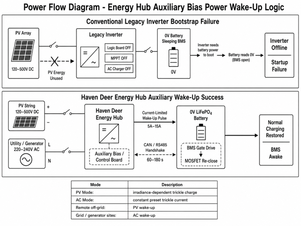
When a battery under-voltage lockout condition is detected, Haven Deer auxiliary control circuitry uses incoming high-voltage PV strings (120V DC to 500V DC) or utility AC / generator input (220V/230V/240V AC) to power the inverter control system:
- Auxiliary Bias Excitation: Incoming solar array voltage or AC utility voltage powers the inverter control board independently of normal battery terminal voltage availability.
- Current-Limited Activation Charge: The inverter enters lithium battery activation mode and applies a controlled low-current charging output to the battery terminals.
- BMS Gate Drive Engagement: The activation charging current provides sufficient electrical conditions for the BMS control circuit to re-enable the internal protection MOSFETs.
- MOSFET Re-closure & Communication Handshake: After detecting a valid charging source, the BMS closes its protection MOSFETs and restores battery terminal connectivity. Closed-loop CAN/RS485 communication between the inverter EMS and master BMS is then re-established.
| Operational Parameter | PV Input Activation Mode | Utility AC / Generator Activation Mode |
|---|---|---|
| Primary Energy Source | Solar PV Array (120V – 500V DC) | Utility Grid or Generator (220V – 240V AC) |
| Inverter Auxiliary Startup | Powered directly by PV String Voltage | Powered directly by AC Utility / Generator Input |
| Activation Current Profile | Solar Irradiance-Dependent Activation Current | Constant Preset Activation Current (5A – 15A) |
| Ideal Application Site | Remote off-grid sites relying primarily on solar generation | Sites equipped with AC grid supply or generator backup through dry-contact control |
3. Step-by-Step Field Recovery Protocol for Installers
Follow this standardized three-phase field recovery protocol when servicing an off-grid residential or commercial energy storage system affected by battery under-voltage lockout.
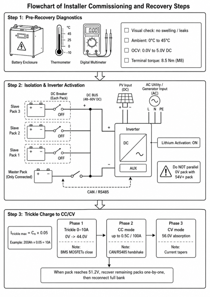
Step 1: Pre-Recovery Diagnostics and Visual Inspection
Before applying any charging current to a locked battery bank, complete the following safety verification steps:
Visual Enclosure Check: Inspect wall-mounted (AL-WM series) or floor-standing mobile cabinet (MB series) enclosures for signs of swelling, mechanical impact, or electrolyte venting.
Thermal Baseline Check: Ensure the battery environment temperature is within the permitted charging range and above 0°C before initiating activation.
Open-Circuit Voltage Measurement: Measure battery terminal voltage with a calibrated digital multimeter. Confirm the reading is near 0.0V DC to 5.0V DC and verify correct polarity before proceeding with UVP recovery.
Installer Pre-Recovery Checklist
☐ Visual inspection: No casing deformation, swelling, or liquid leaks.
☐ Environmental verification: Battery environment temperature is above 0°C and within the approved activation operating range.
☐ Open-circuit measurement: Confirm near-0V DC terminal reading and verify correct polarity before activation.
☐ Physical connection check: Verify terminal torque specifications.
Step 2: System Isolation and Inverter Activation Parameter Setup
To prevent unmanaged current distribution across parallel packs during recovery, isolate individual battery modules:
Isolate Parallel Modules: Disconnect or disable parallel slave battery modules during recovery. Keep only the battery module under activation connected to the inverter DC busbar to prevent uncontrolled current sharing.
Energize Inverter Inputs: Turn on the PV array DC isolator or energize the incoming AC utility/generator input. The Haven Deer hybrid inverter control system will power up through the available auxiliary input source.
Verify Activation Mode: Ensure the inverter lithium battery activation function is enabled. The inverter will apply an appropriate low-current activation charging profile for the connected 48V-class (51.2V nominal) battery bank.
Common Engineering Mistake: Never attempt to jump-start a 0V locked LFP battery bank by directly connecting it in parallel with a fully charged battery bank without current-limiting protection. The unmanaged inrush current can damage DC protection devices, battery terminals, or internal BMS components.
Step 3: Trickle Charge Phase to Constant Current (CC) Transition
Once activation power is applied, monitor the recovery current carefully. Re-establishing baseline cell voltage requires a controlled charging profile.
Activation trickle charging current should be limited to a maximum recommended rate of:
I_trickle_max = C_n × 0.05
Where:
- I_trickle_max = Maximum activation trickle charge current (A)
- C_n = Rated nominal battery capacity (Ah)
For example, when reactivating a 200Ah wall-mounted battery module such as the AL-WM512200:
I_trickle_max = 200Ah × 0.05 = 10A
[Activation Charge Profile]
+-----------------------------------------------------------------------------------+
| BATTERY RECOVERY & THREE-PHASE CHARGING PROCESS                                   |
+-----------------------------------------------------------------------------------+

 [Phase 1: Activation Trickle Charge]
  └── Limited Current Applied Until Battery Terminal Voltage Recovers

                                     │
                                     ▼

 [BMS Protection MOSFETs Close, Terminal Voltage Returns to Normal Range]

                                     │
                                     ▼

 [Phase 2: Constant Current (CC) Mode]
  └── Standard Charging Current Applied According to Battery Specification

                                     │
                                     ▼

 [Phase 3: Constant Voltage (CV) Mode]
  └── Voltage Regulation and Cell Balancing Phase
Trickle Phase: Apply the calculated activation current according to battery capacity. After BMS wake-up, the protection MOSFETs close and the measured terminal voltage returns to the normal battery voltage range.
CAN/RS485 Handshake: Once terminal voltage stabilizes, closed-loop communication is re-established between the master BMS and inverter EMS.
CC Mode Transition: The inverter EMS increases charging current from activation mode to the normal Constant Current (CC) charging profile according to the battery specifications.
Rejoining Parallel Packs: After the recovered battery module returns to a stable operating voltage, repeat the activation process for remaining parallel modules individually before reconnecting the complete battery bank.
4. Critical Safety Boundaries & Engineering Constraints
While LiFePO₄ chemistry provides strong intrinsic thermal stability, recovering deeply discharged cells requires strict adherence to environmental and electrical operating boundaries.
4.1 Thermal Monitoring During Trickle Recovery (Above 0°C Charging Limit)
Lithium iron phosphate batteries must never be charged when cell temperature is below 0°C, as low-temperature charging can cause lithium plating and permanent cell degradation.
+-----------------------------------------------------------------------------------+
| WARNING: LOW-TEMPERATURE CHARGING PROHIBITED                                      |
+-----------------------------------------------------------------------------------+
| • Below 0°C, lithium-ion transport within the graphite anode is reduced.          |
|                                                                                   |
| • Charging under sub-zero conditions can cause metallic lithium plating on the    |
|   anode surface, increasing the risk of internal micro-short circuits and         |
|   permanent capacity degradation.                                                 |
+-----------------------------------------------------------------------------------+
Haven Deer BMS hardware integrates NTC thermal sensors positioned near the prismatic cells to monitor battery temperature during charging and recovery operations.
If battery temperature drops below the charging safety threshold during an under-voltage recovery attempt:
- The BMS protection logic blocks charging commands when the detected battery temperature is below the configured charging safety threshold.
- Charge current remains disabled until battery temperature returns above the configured recovery threshold defined by the BMS temperature hysteresis settings.
- Installers working in cold environments should warm the battery enclosure area to an appropriate operating temperature range before initiating activation commands.
4.2 Parallel Battery Bank Isolation Protocol During Activation
In multi-battery system configurations (such as six parallel 10.24kWh wall-mounted modules), pack state-of-charge imbalance can severely disrupt recovery.
If one battery module has entered UVP protection with a near-0V terminal reading while other parallel modules remain active at approximately 48.0V DC, reconnecting the isolated module directly to the live DC busbar can create a high inrush current:
I_inrush = (V_bus – V_pack_internal) ÷ R_loop
Because total loop resistance (R_loop) across copper busbars and internal battery connections can be extremely low, significant inrush current may occur when a deeply discharged module is reconnected to an energized DC busbar.
Always isolate deeply discharged modules, reactivate each module independently, confirm compatible voltage levels, and reconnect parallel DC isolators only after system conditions are stable.
System designs must follow applicable safety standards, including IEC 62619 for lithium battery systems and IEC 62109-1 / IEC 62109-2 for photovoltaic power converter safety requirements.
5. Preventing Deep Discharge in Off-Grid Microgrids
While Haven Deer hybrid inverters incorporate automated activation functions, preventing deep discharge through proper system configuration remains the preferred engineering approach.
5.1 Configuring Dry Contact Generator Auto-Start Thresholds
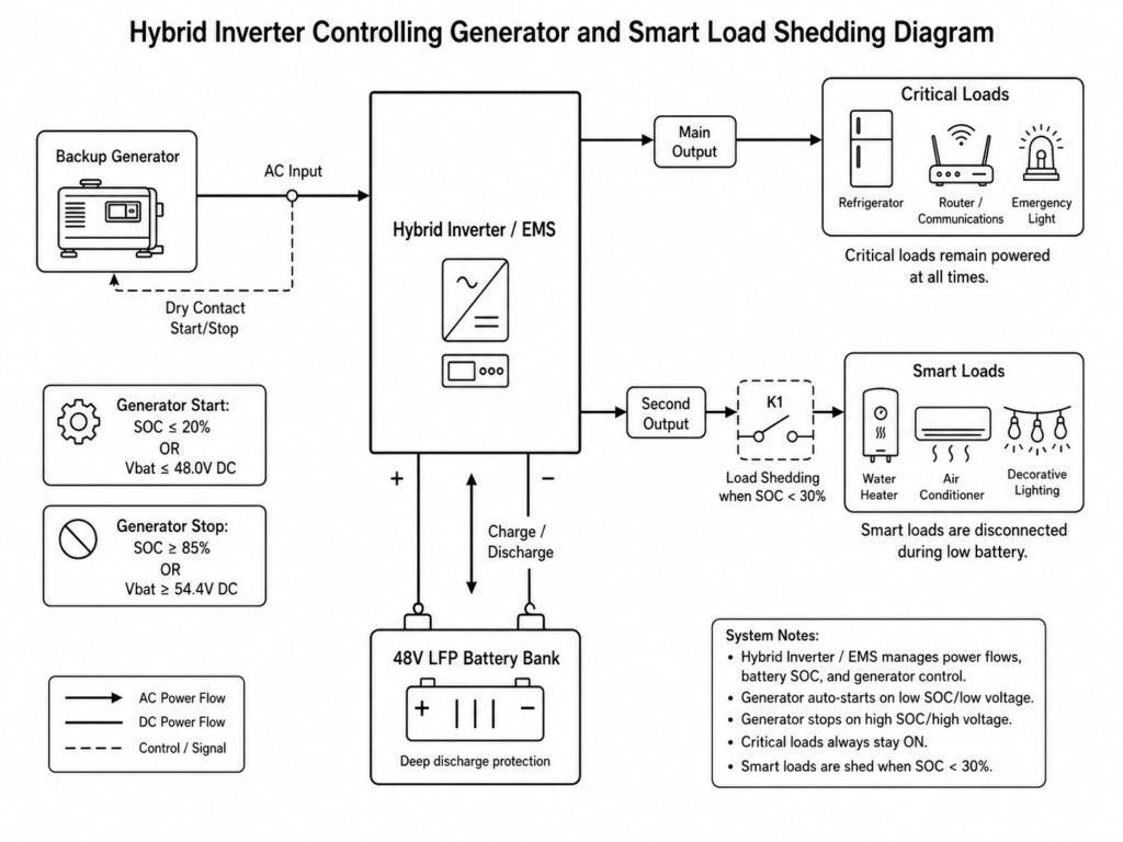
One of the most effective protection strategies against battery depletion in remote off-grid systems is automated auxiliary generator integration. Haven Deer ALL series hybrid inverters support dry contact relay control for integrating backup generators based on configured battery state-of-charge (SOC) or voltage thresholds.
+-----------------------------------------------------------------------------------+
| SYSTEM EMS LOGIC SETUP                                                            |
+-----------------------------------------------------------------------------------+
| [Generator Dry Contact Trigger (Start):]                                          |
| └── Configurable battery SOC or voltage threshold                                 |
|     (for example, SOC ≤ 20% or voltage ≤ 48.0V DC)                                |
|                                                                                   |
| [Generator Dry Contact Trigger (Stop):]                                           |
| └── Configurable recovery threshold                                               |
|     (for example, SOC ≥ 85% or voltage ≥ 54.4V DC)                                |
+-----------------------------------------------------------------------------------+
By configuring the dry contact auto-start trigger at approximately 20% SOC (or 48.0V DC), the inverter can request backup generator operation before the battery bank reaches the 40.0V DC under-voltage protection threshold.
The generator supplies AC power to the inverter AC input, allowing the system to support connected loads while charging the battery bank through the inverter charging circuit.
5.2 EMS Low-Voltage Load Shedding via Dual AC Output
To ensure essential equipment remains operational during extended low-irradiance periods, Haven Deer hybrid inverters feature Dual AC Output architecture:
Main Output (Critical Loads): Feeds essential infrastructure, including refrigeration, communications, routers, and emergency lighting.
Second Output (Smart Load): Feeds non-essential loads, such as water heaters, air conditioning units, or decorative lighting.
When utility grid power is unavailable and battery SOC drops below configured protection thresholds, the Energy Management System (EMS) can transfer or disconnect selected non-essential loads through the Smart Load output.
Conserving remaining battery capacity for essential loads on the Main Output extends backup autonomy and reduces the risk of the battery bank entering deep discharge lockout.
6. Frequently Asked Questions
Why does my 51.2V LFP battery show 0V on a digital multimeter?
The internal BMS has opened its protection MOSFET switches due to Under-Voltage Protection (UVP). This action disconnects the external terminals from the internal cell string to prevent further over-discharge when individual cell voltage reaches the protection threshold.
Can any standard solar inverter reactivate a 0V locked LFP battery?
No. Standard off-grid inverters typically rely on available battery voltage to initialize their internal control circuits. Reactivation requires a hybrid inverter equipped with lithium battery activation capability that can use PV or AC input power to start the recovery process.
How does Haven Deer inverter firmware activate a sleeping BMS?
Haven Deer Energy Hub inverters utilize high-voltage MPPT solar input (120V to 500V DC) or utility AC power to energize inverter control circuitry independently of normal battery startup voltage. The inverter applies a controlled low-current activation charge to restore BMS protection MOSFET operation.
Is a deeply discharged LFP battery permanently damaged?
Not necessarily. If the BMS disconnects near the designed safety cutoff threshold (~2.50V per cell), the battery may remain recoverable. Recovery should be performed using a controlled low-current activation charging profile after confirming battery condition.
What is the maximum safe activation current for a 0V locked battery pack?
Activation trickle current should be limited to approximately 0.05C (for example, 5A for a 100Ah pack or 10A for a 200Ah pack) until the battery pack voltage returns above approximately 44.0V DC (~2.75V per cell).
Can I use a generator to reactivate a locked-out battery bank?
Yes. A generator can supply AC power to the AC input of a compatible Haven Deer hybrid inverter. The inverter uses the available AC input source to execute the lithium battery activation process and restore communication with the connected battery bank.
What happens if I try to charge a deeply discharged LFP pack below 0°C?
BMS firmware will block charging current automatically when battery temperature is below the configured charging limit. Charging LFP cells below 0°C can cause metallic lithium plating on the graphite anode, resulting in permanent capacity degradation and increased internal short-circuit risks.
How long does the reactivation process take?
Initial BMS wake-up typically occurs within several minutes after applying activation power. The recovery time to transition from activation charging to normal charging depends on battery capacity, cell condition, and the applied charging current.
Why shouldn’t I jump-start a 0V LFP pack with a fully charged LFP battery?
Connecting a fully charged battery pack directly to a deeply discharged pack can create uncontrolled inrush current due to the large voltage difference and low circuit resistance. This current surge may damage DC protection components, connectors, or BMS protection circuits.
How can I prevent off-grid LFP batteries from entering UVP lockout?
Configure automatic dry contact generator start thresholds based on system requirements, such as approximately 20% SOC or 48.0V DC, and utilize Dual AC Output smart load management to reduce non-essential loads before critical battery discharge limits are reached.
7. Need Engineering Support for Off-Grid System Sizing or Field Recovery?
Prevent under-voltage lockouts and improve off-grid microgrid reliability through integrated Haven Deer energy storage architectures. Our engineering team provides system design reviews, single-line diagrams, battery sizing calculations, and custom OEM/ODM solutions for distributors, installers, and EPC contractors.