Quick Answer: Inductive motor loads require pure sine wave inverters. Modified sine waves introduce high total harmonic distortion (THD) and rapid dV/dt voltage transitions that degrade electrical performance. Harmonic currents drive up copper and iron losses, generating excess heat, mechanical vibration, audible noise, and insulation stress. High inrush currents can easily trigger startup failure.
1. Understanding Waveform Physics: Pure Sine Wave vs. Modified Sine Wave
In an off-grid solar power system architecture inverters convert DC from batteries and PV arrays into AC power for commercial and residential loads. The switching architecture dictates whether output is a smooth sinusoid or a stepped approximation.
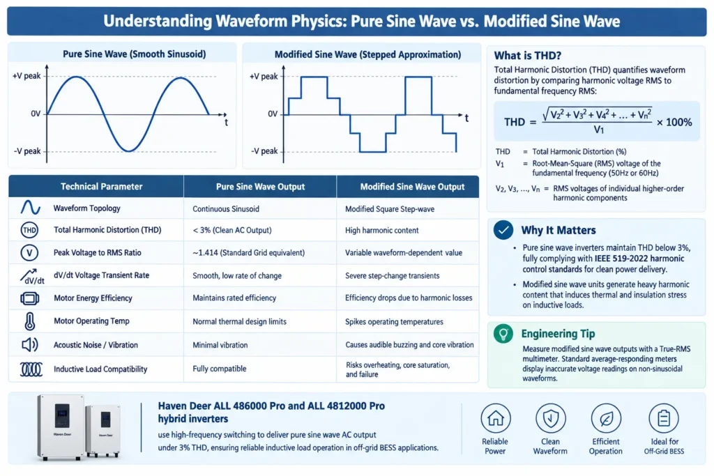
Pure sine wave output matches utility-grade power. Operating at 50Hz or 60Hz, it maintains a predictable voltage rate of change (dV/dt) without abrupt switching transients.
Modified sine waves approximate sinusoids using rectangular voltage pulses. The waveform steps instantly from zero to peak positive voltage, holds, drops through zero, and snaps to peak negative voltage.
Total Harmonic Distortion (THD) quantifies waveform distortion by comparing harmonic voltage RMS to fundamental frequency RMS:
THD = [√(V2² + V3² + V4² + … + Vn²) / V1] × 100%
Where:
THD = Total Harmonic Distortion (%)
V1 = Root-Mean-Square (RMS) voltage of the fundamental frequency (50Hz or 60Hz)
V2, V3, …, Vn = RMS voltages of individual higher-order harmonic components
Pure sine wave inverters maintain THD below 3%, fully complying with IEEE 519-2022 harmonic control standards for clean power delivery. Modified sine wave units generate heavy harmonic content that induces thermal and insulation stress on inductive loads.
| Technical Parameter | Pure Sine Wave Output | Modified Sine Wave Output |
| Waveform Topology | Continuous Sinusoid | Modified Square Step-wave |
| Total Harmonic Distortion (THD) | < 3% (Clean AC Output) | High harmonic content |
| Peak Voltage to RMS Ratio | ~1.414 (Standard Grid equivalent) | Variable waveform-dependent value |
| dV/dt Voltage Transient Rate | Smooth, low rate of change | Severe step-change transients |
| Motor Energy Efficiency | Maintains rated efficiency | Efficiency drops due to harmonic losses |
| Motor Operating Temp | Normal thermal design limits | Spikes operating temperatures |
| Acoustic Noise / Vibration | Minimal vibration | Causes audible buzzing and core vibration |
| Inductive Load Compatibility | Fully compatible | Risks overheating, core saturation, and failure |
Engineering Tip: Measure modified sine wave outputs with a True-RMS multimeter. Standard average-responding meters display inaccurate voltage readings on non-sinusoidal waveforms.
Haven Deer ALL 486000 Pro and ALL 4812000 Pro hybrid solar inverters use high-frequency switching to deliver pure sine wave AC output under 3% THD, ensuring reliable inductive load operation in off-grid BESS applications.
2. Why Inductive Motor Loads Are Exceptionally Sensitive to Waveform Quality
Inductive loads like pumps, HVAC compressors, and power tools rely on electromagnetic induction to generate shaft torque. Built to comply with NEMA MG 1 motor specifications, inductive equipment features heavy magnetic circuits with copper magnet wire wrapped around laminated iron cores.
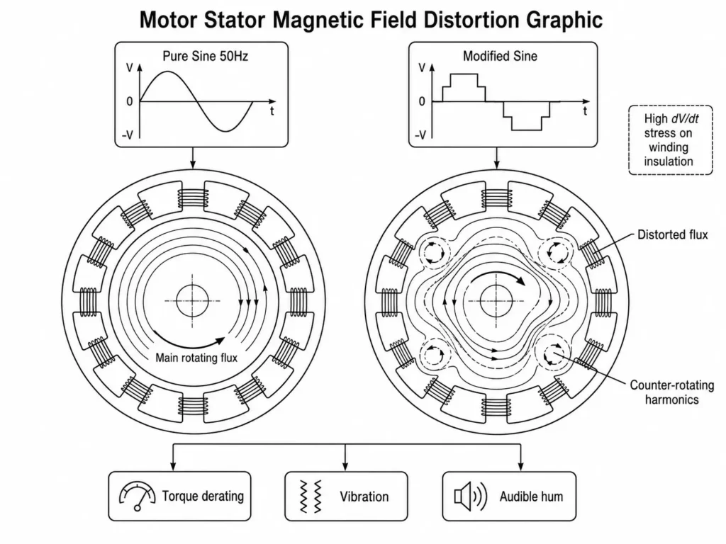
An electric motor presents inductive reactance (X_L) to an alternating current signal, defined by the formula:
X_L = 2 × π × f × L
Where:
X_L = Inductive reactance (Ohms, Ω)
f = Signal frequency (Hertz, Hz)
L = Inductance of motor stator windings (Henries, H)
At a 50Hz pure sine wave baseline, motor reactance regulates current cleanly. Modified sine waves inject heavy harmonic content at odd multiples of the fundamental frequency (3rd = 150Hz, 5th = 250Hz, 7th = 350Hz).
Reactance scales directly with frequency. Consequently, high-order harmonic voltages distort current distribution inside stator windings. Harmonics distort the rotating magnetic field without generating useful torque. Instead, they drive up electromagnetic losses and induce immediate mechanical and thermal stress:
- Torque Derating: The motor produces less usable shaft torque per ampere drawn.
- Mechanical Stress: Harmonic magnetic forces trigger vibration, accelerating mechanical wear on bearings, shaft couplings, and impellers.
- Audible Resonance: Abrupt dV/dt step transitions excite mechanical vibration in stator laminations, generating loud acoustic hum.
Engineering Tip: High dV/dt transitions at step edges induce severe dielectric stress across magnet wire insulation. Over time, this repetitive stress accelerates insulation breakdown, risking inter-turn short circuits.
Haven Deer hybrid inverters act as a central Energy Hub with dual MPPT trackers, delivering stable pure sine wave AC output to protect inductive motor loads in off-grid BESS deployments.
3. Impact of Modified Sine Waves on Motor Life, Thermal Dissipation, and Efficiency
Operating an induction motor on non-sinusoidal waveforms generates heavy energy losses as waste heat. Total thermal loss under distorted AC is calculated as:
P_thermal = (I_fundamental² × R) + ∑ (I_n² × R_n)
Where:
P_thermal = Total heat dissipation in motor windings (Watts, W)
I_fundamental = Current at the fundamental operating frequency (50Hz/60Hz)
I_n = Current contribution from the nth harmonic frequency
R_n = Effective winding resistance at harmonic frequencies considering skin effect (Ohms, Ω)
Harmonic currents (I_n) deliver zero useful torque. Instead, they drive up copper and iron losses inside motor windings and laminations. High-frequency harmonics trigger skin effect, forcing current to conductor surfaces. This elevates effective winding resistance (R_n) and multiplies I²R thermal copper losses. Harmonic magnetic fields also induce severe eddy currents and hysteresis losses inside core laminations.
Modified Wave Input ──► High Harmonic Content ──► Skin Effect & Eddy Currents ──► Thermal Stress ──► Insulation Breakdown
In the field, motors running on distorted AC run significantly hotter than those on pure sine waves. Exact temperature rise depends on motor design, loading, and THD levels.
Under the Arrhenius reaction rate law, thermal elevation accelerates insulation decay. As a field rule of thumb, winding insulation life cuts in half for every 10°C rise above rated thermal limits.
Common Field Mistake: Oversizing a motor to compensate for modified sine wave losses does not eliminate harmonic stress. Oversized motors still suffer harmonic heating, while higher idle current accelerates battery drain in off-grid BESS applications.
4. Inrush Currents and Surge Handling for Motor Loads in Off-Grid ESS
Motor startup creates a severe electrical transient: Locked Rotor Amperage (LRA). At energized standstill, zero Counter-Electromotive Force (CEMF) opposes current flow. At standstill, the stator acts as a direct short circuit.
Inrush spikes current to 3×–7× full-load amperage (FLA) depending on motor design and startup load. For complete system dimensioning, refer to our step-by-step engineering guide to sizing off-grid ESS kits, or calculate required inverter surge capacity using:
P_surge_required = P_motor_rated × K_inrush
Where:
P_surge_required = Required inverter surge capacity during motor startup (VA)
P_motor_rated = Motor running electrical input power requirement (VA)
K_inrush = Motor startup current multiplier (typically 3× to 7×)
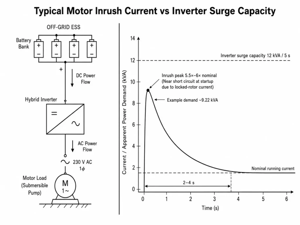
4.1 Step-by-Step Worked Sizing Example
Motor Equipment: 1.1kW (1.5HP) Submersible Well Pump
Electrical Specs: 230V AC, 50Hz, Single-phase, Power Factor (PF) = 0.82, Motor Efficiency (η) = 0.80
Inrush Multiplier: 5.5× nominal current
Step 1: Calculate Continuous Electrical Power Demand (VA)
Continuous Power = P_motor_rated / (PF × η)
Continuous Power = 1100W / (0.82 × 0.80) = 1676.8VA (1.68kVA)
Step 2: Calculate Motor Inrush Surge Demand (VA)
Inrush Surge = Continuous Power × Inrush Multiplier
Inrush Surge = 1676.8VA × 5.5 = 9222.4VA (9.22kVA) for a 2-to-4 second duration.
Step 3: Match with Off-Grid Hybrid Inverter Specs
- Option A (6kW Inverter): The Haven Deer ALL 486000 Pro delivers 6000W continuous power with a 12,000VA (12kVA) 5-second surge peak. The 9.22kVA pump inrush sits safely within this surge envelope.
- Option B (12kW Inverter): The Haven Deer ALL 4812000 Pro delivers 12,000W continuous output with a 22,000VA (22kVA) surge peak, leaving substantial headroom for concurrent inductive loads.
| Motor Application | Typical Power Rating | Inrush Multiplier (K_inrush) | Required Surge Duration | Recommended Inverter Model |
| Domestic Refrigerator | 150W to 300W | 5× to 8× | 0.5 to 1.0s | ALL 486000 Pro (12kVA Surge) |
| Submersible Well Pump | 750W to 2200W | 4× to 7× | 2.0 to 4.0s | ALL 486000 Pro / ALL 4812000 Pro |
| Air Compressor / HVAC | 1500W to 4000W | 3× to 6× | 3.0 to 5.0s | ALL 4812000 Pro (22kVA Surge) |
| Heavy Workshop Tools | 1000W to 3000W | 3× to 5× | 1.0 to 3.0s | ALL 486000 Pro (12kVA Surge) |
4-Step Inductive Load Inverter Sizing Checklist:
[ ] 1. Identify motor nameplate rated power (kW/HP), power factor (PF), and efficiency (η).
[ ] 2. Determine motor Locked Rotor Amperage (LRA) or inrush multiplier (typically 3× to 7×).
[ ] 3. Verify inverter peak surge rating (kVA) and surge hold duration (e.g., 5 seconds).
[ ] 4. Verify battery discharge C-rate and BMS current limits (e.g., Grade A LiFePO4 supplying 200A continuous) to prevent voltage sag trips during peak inrush.
5. Selecting Pure Sine Wave Off-Grid Inverters for Motor Load Applications
Sizing inverters for motor loads requires looking beyond continuous wattage. Installers must evaluate four core engineering criteria:
- Total Harmonic Distortion (THD): Target <3% THD to minimize harmonic losses and winding overheating.
- Surge Capacity & Duration: Match surge ratings to motor LRA across 2–5 second startup windows. The ALL 486000 Pro supplies 12kVA surge, while the ALL 4812000 Pro delivers 22kVA surge.
- Dual AC Load Management: Segregate high-priority inductive loads (pumps, refrigeration) onto primary outputs, shedding non-critical circuits at low SoC.
- Transfer Time: Sub-10ms transfer times prevent motor contactors from dropping out during grid or generator source transitions.
Haven Deer off-grid solar power system packages combine pure sine wave hybrid inverters with Grade A LiFePO4 battery systems—such as the AL-WM512200 wall-mounted home solar battery and MB512346 cabinet off-grid solar battery—delivering stable surge output for heavy inductive loads.ormance for inductive load applications.
6. Frequently Asked Questions
Can an AC induction motor run on a modified sine wave inverter?
Yes, but at the cost of performance and motor lifespan. Modified sine waves generate heavy harmonic losses, excessive heat, and acoustic noise while drastically reducing motor efficiency. Pure sine wave inverters are required for reliable, long-term operation.
Why do electric motors overheat when powered by modified sine wave inverters?
Modified sine waves contain high-frequency harmonics that induce waste heat instead of torque. Harmonic currents drive up copper losses (I²R), eddy currents, and core thermal stress.
What is total harmonic distortion (THD) and why does it matter for pumps?
THD measures waveform deviation from a pure sinusoid. High THD introduces harmonic currents that cause core vibration, thermal stress, and accelerated wear in pumps and compressors.
How do I calculate the inverter surge capacity needed for a water pump?
Multiply running power (VA) by the inrush multiplier (5×–7×). Verify that the hybrid inverter holds or exceeds this peak surge rating for 3 to 5 seconds.
Does a pure sine wave inverter consume more standby power than a modified sine wave inverter?
No. Modern high-frequency pure sine wave inverters deliver high operating efficiency while keeping tare losses comparable to modified wave units.
Will running a refrigerator compressor on a modified wave void its manufacturer warranty?
Frequently, yes. Overheating from distorted waveforms often causes premature compressor failure, which voids OEM warranties. Always verify OEM power quality requirements.
What happens to the battery bank during motor startup in an off-grid solar system?
Motor inrush triggers an immediate high-ampere DC discharge spike. High-discharge Grade A LiFePO4 batteries stabilize the DC bus, preventing BMS low-voltage trips during peak surge.
Are variable frequency drives (VFDs) compatible with pure sine wave solar inverters?
Yes. Pure sine wave inverters supply clean power for VFD rectifier bridges. Modified sine waves distort DC bus voltage and stress VFD input capacitors.
Can Haven Deer hybrid inverters handle heavy motor surge loads without tripping?
Yes. The Haven Deer ALL 486000 Pro (6kW) delivers a 12kVA surge, and the ALL 4812000 Pro (12kW) delivers a 22kVA surge for heavy motor inrush.
Why does my multimeter read lower voltage on a modified sine wave inverter output?
Standard multimeters assume a pure sine wave, miscalculating non-sinusoidal RMS voltage. Accurate voltage readings on non-sinusoidal waveforms require a multimeter operating on the True-RMS measurement principle to properly calculate harmonic voltage components.
7. Need Custom System Design for Heavy Inductive Motor Loads?
Heavy motor loads demand precise surge sizing. Off-grid BESS design for pumps, compressors, and machinery requires exact LRA surge calculations and battery C-rate matching.
Contact Haven Deer application engineers for single-line diagrams (SLDs), BESS sizing validation, or custom OEM/ODM project support.