Quick Answer: Weak-grid commercial sites require high-capacity PV arrays, Grade A LiFePO4 storage, multi-input hybrid inverters, and automated generator controls. During grid sags, hybrid inverters transfer critical loads to battery power within 10ms. This sub-cycle switching isolates sensitive equipment from voltage and frequency instability. Facilities manage peak demand without relying on an unstable utility.
1. Understanding Weak-Grid Challenges in Light Commercial & Industrial Applications
Commercial facilities in rural and remote areas face severe grid instability from weak distribution networks, long transmission lines, and capacity bottlenecks. Weak grids deliver severe voltage fluctuations, frequency drift, brownouts, and unexpected outages. Running light commercial and industrial (C&I) loads on unstable feeds damages equipment and triggers downtime.
1.1 Key Electrical Vulnerabilities: Sags, Surges, and Frequency Drift
Standard grid-tied PV inverters require a stable AC grid voltage and frequency reference. On a weak grid, this dependency forces frequent trips:
- Voltage Sags and Brownouts: Line voltage drops force heavy loads (pumps, compressors, CNC machinery) to draw excessive current, overheating motor windings.
- Frequency Instability: Frequency excursions outside protection limits trigger inverter anti-islanding, killing solar generation even while utility power is present.
- Transient Voltage Surges: Switching high-inductive loads across long lines spikes voltage, damaging sensitive control boards and communication hardware.
- Harmonic Distortion: Poor waveform quality inflates Total Harmonic Distortion (THD) beyond IEEE 519 power quality limits, heating transformers and accelerating drive failure.
When grid parameters drift outside protection windows, standard inverters trip offline. Solar generation drops to zero immediately.
| Weak-Grid Electrical Anomaly | Underlying Cause | Equipment Operational Risk | Impact on Standard Grid-Tied PV |
| Voltage Sag (<85% Unom) | Insufficient transformer capacity and long line impedance | Motor overheating, relay chatter, VFD tripping | Inverter anti-islanding trip |
| Frequency Drift (±2.0 Hz) | Unbalanced supply and demand on utility feeder | Clock desynchronization, motor speed variation | Possible inverter disconnection |
| Transient Surges (>120% Unom) | Utility switching and atmospheric discharge | Control board damage, insulation stress | High-voltage fault shutdown |
| Extended Brownout | Peak feeder demand exceeding supply capacity | Production interruption and equipment stress | Loss of solar self-consumption |
1.2 The Economic Impact of Unstable Utility Grid Connections
Cold storage, agricultural processing, textile manufacturing, and telecom hubs suffer immediate revenue loss from power interruptions. Outages spoil inventory, halt production, and rack up idle labor costs.
Running diesel generators as primary backup drives up OPEX through fuel burn, rapid maintenance cycles, and high emissions.
An integrated off-grid BESS slashes diesel reliance. Combining solar PV, LiFePO4 storage, and auto-start generator controls limits genset runtime purely to emergency backup.
2. Core Architecture of a Commercial Weak-Grid Solar ESS Kit
Resolving weak-grid vulnerabilities requires moving beyond standard grid-tied PV to a modern off-grid BESS architecture. This setup acts as a dynamic energy buffer between the utility and critical C&I loads.
2.1 Multi-Input Energy Management Hub Topology
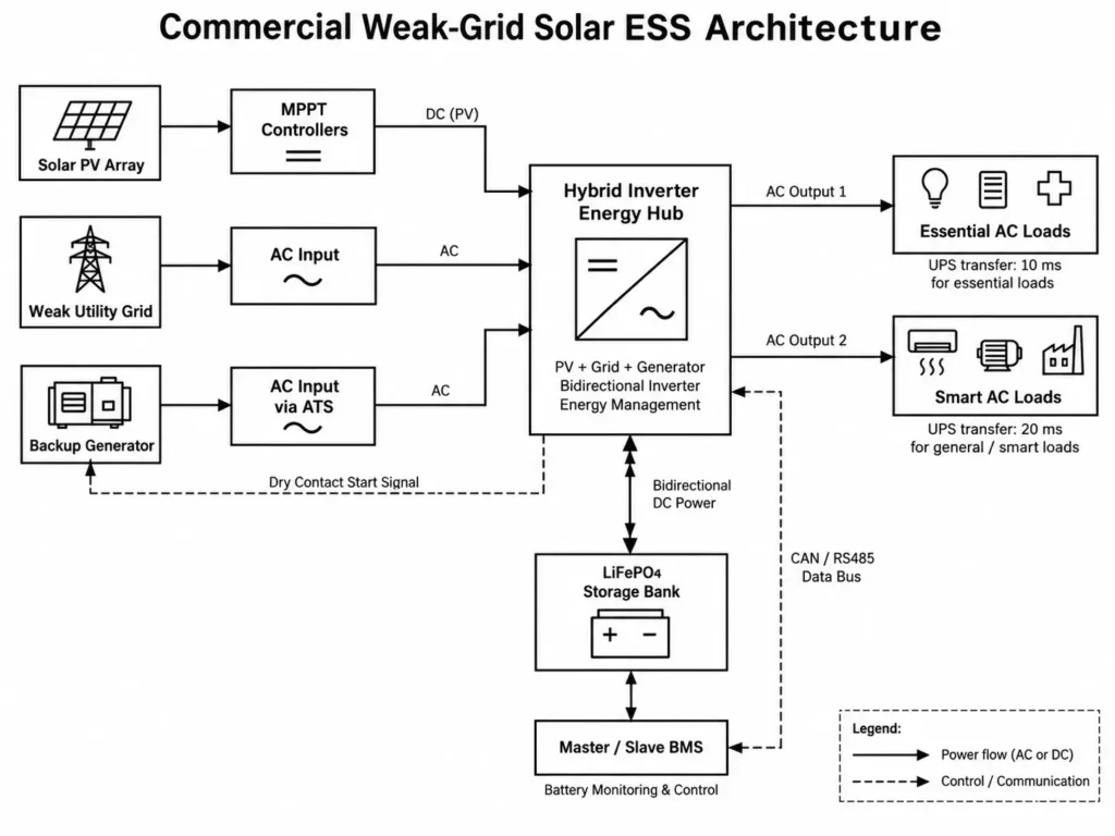
A low-voltage hybrid inverter anchors this architecture. Instead of just converting DC to AC, it actively coordinates PV generation, battery dispatch, grid power, and genset backup.
The architecture separates power circuit pathways from high-speed control logic:
- Power Circuit (Energy Flow): PV arrays, the utility grid, and AC generators feed the hybrid inverter. The system dynamically routes this power to charge the LiFePO₄ bank, drive AC loads, or reserve backup capacity via EMS logic.
- Control Circuit (Data Flow): A high-speed CAN or RS485 bus links the battery BMS directly to the inverter EMS.
Units like the ALL 4812000 Pro hybrid inverter use bidirectional conversion and EMS dispatch to isolate critical loads from unstable grid conditions.
2.2 Uninterrupted Power Supply (UPS) Transfer Mechanics (10ms Switching)
During grid outages or severe sags, the hybrid inverter instantly shifts to battery backup. This keeps connected loads powered without interruption.
The internal automatic transfer switch achieves distinct transfer speed tiers:
- 10ms Transfer: Protects sensitive electronics like servers, PLCs, and telecom gear. This sub-cycle switch beats short ride-through limits, preventing reboot cycles.
- 20ms Transfer: Supports standard C&I loads like lighting, compressors, and motor-driven appliances.
3. Dynamic Operating Strategies: SBU, SUB, and Peak-Shaving Logic
System resilience hinges on EMS dispatch logic. Selecting the right operating mode balances power availability, battery degradation, and backup runtime.
3.1 SUB Mode vs. SBU Mode for Variable Grid Quality
The hybrid inverter EMS dispatches power based on solar yield, battery state of charge (SoC), grid quality, and load demand.
SUB Mode (Solar → Utility → Battery):
- Dispatch Priority: PV powers loads first. If solar falls short, grid power supplements the load before drawing from the battery.
- Engineering Application: Best for sites with frequent voltage sags but active utility feeds. SUB mode relies on grid power during normal operation, preserving battery SoC for complete outages.
SBU Mode (Solar → Battery → Utility):
- Dispatch Priority: PV powers loads first, routing excess to the battery. If solar drops, the battery discharges to cover the deficit. The grid acts as a last-resort backup when the battery hits its low-SoC cut-off.
- Engineering Application: Ideal for high-tariff regions with reliable solar yield. SBU maximizes self-consumption and slashes grid reliance.
| Parameter | SBU Mode (Solar → Battery → Utility) | SUB Mode (Solar → Utility → Battery) |
| Primary Power Source | Solar PV + LiFePO₄ Battery Bank | Solar PV + Utility Grid |
| Grid Role | Backup source after battery reaches configured SOC threshold | Primary supplement when solar generation is insufficient |
| Battery Reserve Status | Cycled according to solar availability and load demand | Maintains higher SOC for emergency backup |
| Target Grid Condition | High electricity tariffs; predictable solar availability | Frequent voltage sags; weak grid stability |
| System Resiliency | Balanced (Battery cycles according to solar availability and load demand) | Higher backup readiness (Battery maintains higher reserve SOC) |
Engineering Tip: Zero-export mandates on weak networks require closed-loop CT sensors or smart meters tied to inverter firmware. Never guarantee zero-export without CT hardware on the single-line diagram.
3.2 Protecting Essential Loads via Dual AC Output Management
During off-grid operation, commercial electrical panels must split into essential and non-essential circuits. Advanced hybrid inverters rely on Dual AC Output engineering for Main and Smart load management to automate circuit shedding:
- Main Output Terminal: Supplies critical circuits—PLCs, security, refrigeration, and emergency lighting. Power remains online as long as battery reserves last.
- Second Output Terminal (Smart Load): Powers non-critical loads like comfort HVAC, secondary pumps, and water heaters.
If a grid outage hits during low solar output, the EMS tracks battery SoC. When SoC drops below the configured setpoint, the EMS trips the Second Output contactor. Shedding secondary loads extends critical backup runtime automatically.
4. Scalable Inverter Architecture & Parallel Expansion Design
Commercial loads often exceed single-inverter limits. Motor-driven industrial equipment creates massive startup surges, demanding conservative inverter sizing.
4.1 Sizing 12kW Dual MPPT Inverters for Inductive Surge Loads
Inductive loads like compressors, deep-well pumps, and conveyors draw peak startup power up to 5x their continuous rating. Sizing inverters strictly on continuous demand trips overcurrent protection during motor startup.
To calculate required surge capacity for inductive machinery, apply the following calculation:
Psurge = Prated × kstart
Where:
- Psurge = Required inverter peak surge capacity (kVA)
- Prated = Rated motor running power (kW)
- kstart = Motor starting power multiplier (typically 3.0 for VFD-driven motors; 4.0 to 5.0 for direct-on-line motors)
The ALL 4812000 Pro delivers 12kW continuous output and handles 22kVA surges for up to 5 seconds. This headroom absorbs heavy motor inrush currents.
Dual MPPT channels support PV input voltages up to 500V DC across an operating range of 60–500V DC. In cold environments, string design must account for voltage rise driven by negative temperature coefficients:
Voc,max = Voc,STC × [1 + (γVoc / 100) × (Tmin – 25°C)] × Nseries
Where:
- Voc,max = Maximum expected string open-circuit voltage at cold site conditions (V DC)
- Voc,STC = Open-circuit voltage per panel under Standard Test Conditions (V DC)
- γVoc = Temperature coefficient of Voc (%/°C, typically negative, e.g., -0.28%/°C)
- Tmin = Lowest expected ambient temperature at the installation site (°C)
- Nseries = Number of PV solar modules connected in series per string
Calculated Voc,max must stay below the 500V DC ceiling at record cold temperatures. Overvoltage destroys MPPT input stages.
Commercial Site Sizing Example: Agricultural Processing Workshop
Site Demand Profile:
- Continuous Baseline Load: 18 kW
- Peak Motor Surge Load: 32 kVA (Direct-on-Line Water Pumps)
- Daily Energy Consumption: 90 kWh/day
- Minimum Temperature (Tmin): -10°C
Calculated System Sizing Solution:
- Inverter Configuration: 2 x ALL 4812000 Pro Inverters connected in parallel ──► Combined Continuous AC Output: 24 kW (Exceeds 18 kW baseline) ──► Combined Peak Surge Capacity: 44 kVA for 5 seconds (Exceeds 32 kVA peak surge)
- Solar Array Sizing: 20 kWp PV Array utilizing 610W Monocrystalline Modules ──► String Design: 8 modules per string (Voc,STC = 49V; Voc,max at -10°C = ~442V DC per string; well within the 60–500V DC MPPT window)
- Energy Storage Capacity: 3 x MB512300 Floor-Standing Cabinet Batteries (15kWh each) ──► Total Storage Energy: 45 kWh nominal storage capacity (Designed to support approximately 50% of overnight load demand based on the example operating profile)
- Auxiliary Generator: 12 kW Diesel Generator integrated via Dry Contact relay
4.2 Multi-Unit Parallel Configuration (Up to 6 Units / 72kW Output)
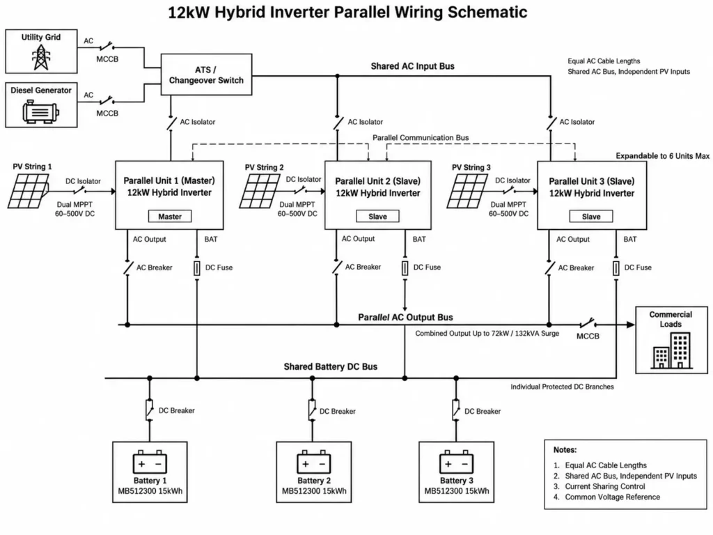
When site demand exceeds 12kW, applying sound inverter parallel operation engineering allows stacking compatible units on a common AC busbar using dedicated communication links and current-sharing logic.
- Equal Cable Lengths: Match conductor gauge and length from each inverter to the central AC busbar. Equal impedance prevents current imbalance.
- Shared Battery Busbar: Connect all parallel units to a single DC busbar. This maintains uniform DC voltage across all inverters.
- Communication Daisy-Chain: Daisy-chain parallel units via dedicated sync cables. Designate one unit as Master and the remaining units as Slaves.
| Parallel Inverter Count | Continuous AC Output Power | Peak Surge Power (5 Sec) | Max PV Array Input Capacity | Max Solar Charging Current |
| 1 Unit | 12 kW | 22 kVA | 15.0 kW | 160 A |
| 2 Units | 24 kW | 44 kVA | 30.0 kW | 320 A |
| 3 Units | 36 kW | 66 kVA | 45.0 kW | 480 A |
| 4 Units | 48 kW | 88 kVA | 60.0 kW | 640 A |
| 6 Units (Maximum) | 72 kW | 132 kVA | 90.0 kW | 960 A |
5. Automated Generator Integration & Dry Contact Relay Logic
Prolonged low solar yield drains battery reserves on weak or off-grid sites. Adding an automated backup generator ensures continuous power during extended low-generation periods.
5.1 Passive Dry Contact Trigger Thresholds (SoC % vs. Voltage)
Hybrid inverters execute automated generator integration via passive dry contact relays to control start and stop signals. This volt-free switch (NO/NC) connects to the generator remote-start terminal, ATS, or control panel.
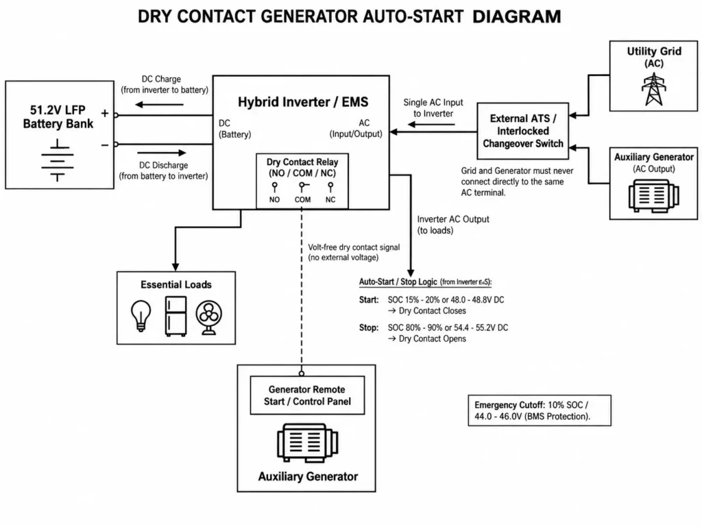
The EMS manages the dry contact relay state according to user-configurable battery thresholds:
- Start Signal Trigger: When battery SoC drops to setpoint (e.g., 20% SoC or 48.0V DC under load), the inverter closes the dry contact. This triggers the generator startup sequence: engine cranking, warm-up, and load transfer.
- Stop Signal Trigger: While the generator charges the battery bank, the EMS monitors live SoC. Once the battery reaches the upper setpoint (85%–90% SoC), the dry contact opens, initiating engine cool-down and shutdown.
| Control Parameter | Recommended SoC Setting | Voltage Equivalent (51.2V LFP) | Operational Objective |
| Generator Auto-Start Threshold | 15% – 20% SoC | 48.0V – 48.8V DC | Prevent deep discharge; activate auxiliary power source |
| Generator Auto-Stop Threshold | 80% – 90% SoC | 54.4V – 55.2V DC | Restore battery reserve; reduce generator runtime |
| Low-Battery Emergency Cutoff | 10% SoC | 44.0V – 46.0V DC | Final battery protection threshold controlled by BMS safety logic |
5.2 Single-AC Input Terminal Sharing Rules (Grid vs. Generator)
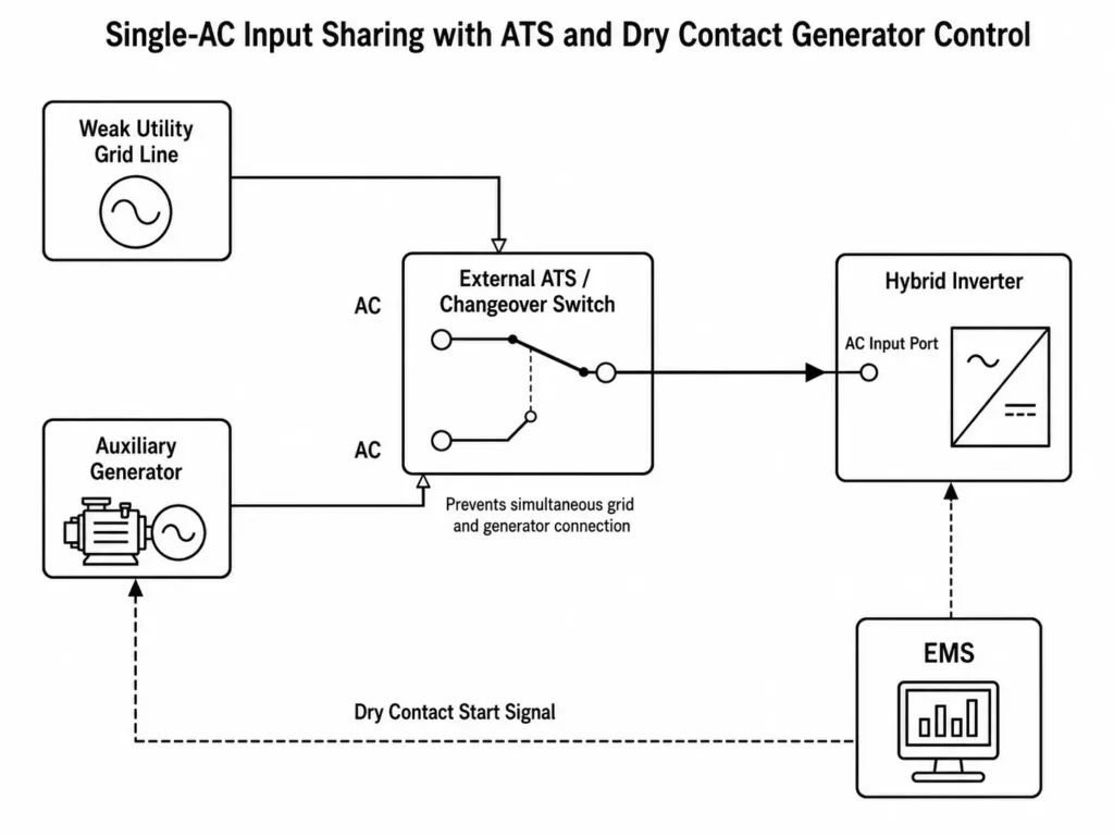
Common Mistake: Wiring utility grid and generator lines directly to the same inverter AC terminal causes catastrophic backfeeding and hardware failure.
The hybrid inverter features a single AC input terminal. Utility power and generator output must never connect simultaneously. When deploying both sources, install an external ATS or interlocked changeover switch before the AC input. Unisolated AC inputs destroy inverter power stages.
6. Battery Bank Sizing & Enclosure Selection: Wall-Mounted vs. Floor Cabinet
Commercial off-grid BESS demands long cycle life, stable discharge, and thermal control. LiFePO₄ chemistry dominates this space through its superior thermal stability and cell safety characteristics.
6.1 Selecting High-Capacity LFP Floor Cabinets (15kWh–18kWh Modules)
Commercial weak-grid sites require larger capacities than residential wall-mounted units can deliver. Heavy wall-mounted packs risk structural wall failure.
Deploying floor-standing mobile cabinet batteries like the MB512300 (15.0kWh) and MB512346 (18.0kWh) offers clear engineering advantages:
- Structural Support and Mobility: Floor cabinets rest heavy battery weight directly on the pad, bypassing wall structural limits. Built-in casters simplify positioning during installation.
- Thermal Protection: Spacious cabinet interiors provide airflow channels around Grade A prismatic cells, improving passive heat dissipation and cell stability.
- Protection Ratings: Indoor C&I deployments demand adequate ingress protection. Wall units typically feature IP21 enclosures, while floor cabinets carry IP22 ratings to resist solid objects and condensation drips.
| Technical Specification | Wall-Mounted Battery (AL-WM512200) | Floor Cabinet Battery (MB512300) | Floor Cabinet Battery (MB512346) |
| Nominal System Energy | 10.24 kWh | 15.0 kWh | 18.0 kWh |
| Nominal System Voltage | 51.2V DC (16S) | 51.2V DC (16S) | 51.2V DC (16S) |
| Rated Storage Capacity | 206Ah | 300Ah | 346Ah |
| Continuous Current Rating | 200A Charge / Discharge | 150A Charge / 200A Discharge | 150A Charge / 200A Discharge |
| Form Factor / Mounting | Wall-Mounted | Floor-Standing Mobile Cabinet | Floor-Standing Mobile Cabinet |
| Net Hardware Weight | 102 kg | 129 kg | 163 kg |
| Enclosure Rating | IP21 | IP22 | IP22 |
| Cycle Life Performance | ≥6,000 Cycles @ 90% DoD | ≥6,000 Cycles @ 90% DoD | ≥6,000 Cycles @ 90% DoD (25°C operating condition) |
6.2 BMS Master-Slave Protocol for Large Commercial Storage Arrays
Paralleling LiFePO₄ modules requires daisy-chained communication cables to build a Master-Slave BMS network.
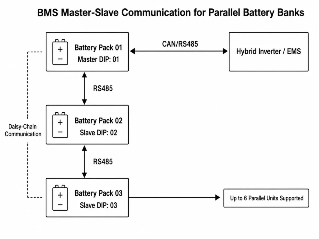
- DIP Address Configuration: Hardware DIP switches set individual unit addresses. Configure Pack 01 as address 01 (Master BMS) and set subsequent units to 02, 03, and 04 (Slave BMS).
- Data Aggregation: Slave units relay cell voltages, pack temperatures, charge currents, and individual SoC over internal RS485 to the Master BMS.
- Inverter Synchronization: The Master BMS aggregates slave telemetry and broadcasts total system SoC, combined charge/discharge limits, and battery health to the inverter EMS via CAN or RS485.
Engineering Tip: Stop lithium battery charging below 0°C. Charging at sub-zero temperatures causes lithium plating on graphite anodes, triggering permanent capacity loss. Insulate or heat battery rooms in cold climates. Discharging remains safe down to -15°C or -20°C depending on pack specifications.
7. IEC Compliance, System Commissioning, and Installation Safety
Deploying weak-grid commercial BESS hardware requires strict safety standard compliance, dedicated DC circuit protection, and structured commissioning.
7.1 IEC 62109-1 / IEC 62109-2 Standards & Protection Ratings
Commercial off-grid solar equipment must align with the IEC 62109-1 / IEC 62109-2 compliance guide and core international safety standards:
- IEC 62109-1: Governs power conversion safety in PV systems, mandating strict electrical insulation, shock protection, and thermal thresholds.
- IEC 62109-2: Covers PV inverter design, enforcing DC input isolation, fault protection, and active safety shutdown.
- UL 1741: Certifies grid-interconnection safety for inverters, charge controllers, and transfer switches in North American markets.
- Electromagnetic Compatibility (EMC): Compliance with EN 61000-6-1 and EN 61000-6-3 prevents noise interference and protects sensitive control electronics in C&I environments.
Array DC Protection: Multi-string arrays require an IP65 PV combiner box between the solar field and inverter MPPT inputs. Install:
- Class II DC SPDs (20–40kA, 500V DC)
- 2-Pole DC circuit breakers (63A)
- Individual string DC fuses (32A, 500V DC)
7.2 Step-by-Step Commissioning Checklist for Engineering Contractors
Complete this commissioning checklist before energizing a weak-grid commercial BESS:
| Verification Phase | Inspection Item | Engineering Verification Standard | Status |
| 1. Mechanical & Mounting | Inverter & Battery Mounts | Verify wall anchor load capacity or concrete floor levelness according to installation requirements. | [ ] Pass |
| 2. DC String Isolation | PV Array Open Circuit Voltage | Measure string Voc; verify voltage is below 500V DC under the lowest expected operating temperature conditions. | [ ] Pass |
| 3. Grounding & Earthing | System Ground Continuity | Verify grounding continuity between the solar frame, combiner box, inverter chassis, and earth grounding system according to local electrical requirements. | [ ] Pass |
| 4. DC Polarity Check | Battery & PV Connections | Verify correct positive (+) and negative (-) polarity on all terminals using a digital multimeter (DMM). | [ ] Pass |
| 5. Communication Bus | BMS-Inverter Data Lines | Verify DIP switch addressing and confirm CAN/RS485 closed-loop communication between battery BMS and inverter EMS. | [ ] Pass |
| 6. AC Input/Output Isolation | AC Phase & Voltage Lines | Confirm correct separation and wiring between Main Output, Smart Load, and AC Input terminals. | [ ] Pass |
| 7. Generator Integration | Dry Contact Relay Signal | Test the Dry Contact start signal at generator ATS terminals using a simulated low SoC trigger. | [ ] Pass |
| 8. Firmware Commissioning | EMS Operating Parameters | Configure operating strategies (SUB/SBU), transfer settings, and maximum battery charging current parameters according to system design requirements. | [ ] Pass |
8. Frequently Asked Questions
How does a hybrid inverter handle sudden voltage sags on a weak grid?
The hybrid inverter EMS continuously monitors AC input quality. When grid voltage drops below 85% nominal, the inverter transfers loads to battery/PV power within 10ms. Sub-cycle transfer prevents equipment shutdowns.
Can I connect both the utility grid and a diesel generator to the same hybrid inverter?
Yes, but never simultaneously. Wire utility power and generator lines through an external ATS or interlocked changeover switch ahead of the AC input terminal. Unisolated AC inputs destroy power stages.
What is the transfer time during a sudden utility blackout?
Transfer time is 10ms for sensitive loads (servers, PLCs, telecom gear) and 20ms for standard C&I loads like lighting, HVAC, and motors.
How many 12kW hybrid inverters can be connected in parallel for larger commercial loads?
Parallel up to 6 ALL 4812000 Pro units on a common AC busbar. This delivers 72kW continuous output and 132kVA surge capacity.
How does the system automatically trigger a backup generator?
The inverter uses a passive dry contact relay wired to the generator remote-start terminal. When battery SoC drops below setpoint (e.g., 20%), the contact closes to crank the generator. When SoC reaches the upper threshold (85%), the contact opens, initiating engine cool-down.
What happens if the battery bank drops to 0% during an extended grid outage?
The EMS triggers generator auto-start at 15–20% SoC. Without a generator, the inverter executes a low-voltage protection trip. PV array generation automatically cold-starts system recovery once sunlight returns.
What is the maximum PV input voltage supported by 12kW hybrid inverters?
Maximum PV open-circuit voltage (Voc) is 500V DC across a 60–500V DC dual MPPT operating window.
Why are floor-standing mobile cabinets preferred over wall-mounted batteries for commercial projects?
C&I energy storage requires larger pack capacities (15kWh–18kWh). Floor cabinets rest heavy battery weight (129kg–163kg) directly on the slab, feature IP22 enclosures, and eliminate wall structural strain.
Does the system support automatic non-essential load shedding during grid failures?
Yes. Hybrid inverters feature Dual AC Outputs. During grid outages, the EMS trips the Smart Load terminal when battery SoC hits a low setpoint, preserving battery capacity for critical loads on the Main Output.
What certifications do Haven Deer commercial hybrid systems hold?
Haven Deer commercial hybrid systems comply with IEC 62109-1, IEC 62109-2, UL 1741, EN 61000-6-1, and EN 61000-6-3 safety and EMC standards.
Can I expand system battery capacity at a later date?
Yes. Expand up to 6 LiFePO₄ battery packs in parallel. DIP switch addressing configures slave units while the Master BMS coordinates overall array dispatch.
What routine maintenance is required for Grade A LiFePO₄ commercial batteries?
LiFePO₄ batteries require zero fluid or chemical maintenance. Integrated BMS controls automated cell balancing, thermal protection, and active monitoring.
9. Engineering Support & Project Consultation
Weak-grid commercial projects demand rigorous load profiling, surge analysis, parallel sizing, and protection coordination. Haven Deer provides turn-key C&I BESS kits featuring Grade A LiFePO₄ chemistry, multi-input Energy Hub inverters, and integrated EMS controls.
Need a Customized Off-Grid BESS Architecture for Your Commercial Site? Contact our application engineering team to review your single-line diagram, analyze load profiles, and configure a multi-input BESS tailored to your site constraints.