Quick Answer: The split between a 51.2V 100Ah vs 200Ah battery module comes down to three physical constraints: continuous current, inverter pairing, and wall load capacity.
- 102Ah Module (AL-WM512100): Delivers 100A continuous discharge at a 45.5kg net weight. Pairs directly with 3kW–6kW hybrid inverters on standard residential load-bearing walls.
- 206Ah Module (AL-WM512200): Delivers 200A continuous discharge at 102kg. Built for 6kW–12kW hybrid inverters, high-surge inductive loads, and reinforced concrete mounting.
Sizing a residential or light commercial off-grid solar power system goes beyond nameplate kilowatt-hours. Continuous discharge current, inverter matching, structural dead-load limits, and expansion headroom dictate whether 5.12kWh (102Ah) or 10.24kWh (206Ah) modules fit the job.
1. Technical Parameter Breakdown: 51.2V 100Ah vs 200Ah battery
Module engineering starts at cell topology. Both the Haven Deer AL-WM512100 (102Ah) and AL-WM512200 (206Ah) wall-mounted home solar batteries utilize grade a lifepo4 cells in a 16S series string, establishing a standard 51.2V DC bus.
1.1 Cell Architecture & Energy Capacity Calculations
Pack nominal voltage derives directly from the 16S cell series:
V_nominal = 16 × 3.2V = 51.2V
Nominal stored energy (E_kWh) follows standard cell capacity integration:
E_kWh = (V_nominal × Q_Ah) / 1000
For the 102Ah module: E_102Ah = (51.2V × 102Ah) / 1000 = 5.22 kWh theoretical capacity (nameplate rating: 5.12 kWh)
For the 206Ah module: E_206Ah = (51.2V × 206Ah) / 1000 = 10.55 kWh theoretical capacity (nameplate rating: 10.24 kWh)
Both units share the 51.2V LiFePO4 baseline. However, internal busbar sizing, BMS shunt ratings, and thermal mass diverge sharply to manage the 2x continuous discharge spread.
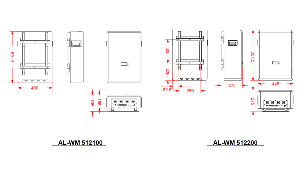
1.2 Technical Parameter Comparison
| Technical Parameter | AL-WM512100 (102Ah Module) | AL-WM512200 (206Ah Module) |
| Nominal Voltage | 51.2V | 51.2V |
| Nominal Energy Capacity | 5.12 kWh | 10.24 kWh |
| Cell Configuration | 16S Grade A LiFePO4 Prismatic | 16S Grade A LiFePO4 Prismatic |
| Operating Voltage Range | 40.0V – 58.4V | 40.0V – 58.4V |
| Continuous Charge / Discharge | 100A / 100A | 200A / 200A |
| Peak Discharge Current | 105A (60s) / 130A (3s) | 210A (60s) / 260A (3s) |
| Cycle Life (90% / 80% DoD) | ≥ 6,000 / ≥ 10,000 cycles | ≥ 6,000 / ≥ 10,000 cycles |
| Dimensions (W × H × D) | 601.5 × 400 × 155 mm | 651.5 × 445 × 235 mm |
| Net Module Weight | 45.5 kg | 102 kg |
| Enclosure Protection | IP21 | IP21 |
Field Note: Check cell delta-V across the 16S string before initial sign-off. The onboard BMS tracks cell voltage spread in real time, triggering passive balancing to prevent premature low- or high-voltage cutoffs under load.
2. Electrical Sizing & Continuous Output Matching with Hybrid Inverters
Battery bank sizing demands direct alignment between continuous DC discharge capacity and maximum inverter draw. Undersizing trips BMS overcurrent protection, throttles inverter throughput, or drops the DC bus below cutoff under heavy surge loads.
2.1 100A vs. 200A Continuous Discharge Limits
Continuous DC output power (P_discharge) tracks instantaneous terminal voltage (V_operating) against the maximum continuous discharge limit (I_continuous):
P_discharge = V_operating × I_continuous
At the nominal battery voltage of 51.2V:
- 102Ah Module (100A Limit): P_discharge = 51.2V × 100A = 5,120W (5.12kW)
- 206Ah Module (200A Limit): P_discharge = 51.2V × 200A = 10,240W (10.24kW)
As voltage sags toward the low-voltage cutoff under load, continuous DC delivery drops:
- 102Ah Module at 42V: P_discharge = 42.0V × 100A = 4,200W (4.20kW)
- 206Ah Module at 42V: P_discharge = 42.0V × 200A = 8,400W (8.40kW)
2.2 Matching 6kW and 12kW Hybrid Inverters
A single-phase 6kW hybrid inverter, such as the Haven Deer ALL 486000 Pro, draws up to 120A continuous DC at rated AC output.
A single 100A pack bottlenecks a 6kW inverter. Pairing the ALL 486000 Pro with one AL-WM512100 caps output between 4.2kW and 5.0kW as pack voltage falls during discharge.
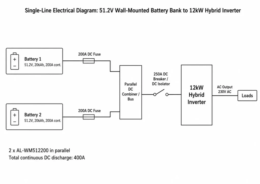
Unlocking full 6kW inverter capacity requires either two AL-WM512100 (102Ah) modules in parallel or a single AL-WM512200 (206Ah) module delivering 200A continuous discharge.
On higher-capacity systems running the Haven Deer ALL 4812000 Pro (12kW output / 22kVA surge), DC bus current at 48V routinely exceeds 250A at full load and spikes higher on inductive surges. Understanding single MPPT vs dual MPPT designs is essential for array matching, because the Pro’s dual MPPT architecture lets you split the PV array across two independent inputs to sustain baseline charge rates.
Run at least two AL-WM512200 (206Ah) modules in parallel to supply this 250A+ bus demand safely.
| Hybrid Inverter Model | Rated Output | Max DC Input Current | Recommended Minimum Battery Setup | Total Continuous DC Discharge |
| ALL 486000 Pro | 6.0kW | 120A | 1 × AL-WM512200 (206Ah) OR 2 × AL-WM512100 (102Ah) in parallel (full rated throughput) | 200A (10.24kW) |
| ALL 4812000 Pro | 12.0kW | 250A | 2 × AL-WM512200 (206Ah) in parallel (sustains full 12kW load without thermal throttling) | 400A (20.48kW) |
3. Structural Mechanics & Wall Load-Bearing Requirements
Solar battery wall mounting clears valuable floor space in tight plant rooms. However, dead load and anchor shear demand structural sign-off before the units are delivered.
3.1 Wall Mounting Mechanics: 45.5kg vs. 102kg Deployment
The mounting bracket translates module dead weight into downward shear and upper tensile pull-out forces.
+-----------------------------------------------------------------------------------+
| BATTERY MODULE MOUNTING FORCE DIAGRAM                                             |
+-----------------------------------------------------------------------------------+
|                                                                                   |
|    Pull-Out Tensile Force (T)                                                     |
|       ◄═════════════════╗                                                         |
|                         ║  [Battery Module]                                       |
|                         ║  Weight (W)                                             |
|                         ║  ↓ Shear Force                                          |
|                         ╝                                                         |
|                                                                                   |
+-----------------------------------------------------------------------------------+
- AL-WM512100 (45.5 kg / 100 lbs): A two-person crew can hang this unit directly onto solid brick, concrete block, or reinforced timber/steel studs with rated backing plates.
- AL-WM512200 (102 kg / 225 lbs): Exceeds two-person safe manual lift limits in tight spaces. Anchor exclusively into reinforced concrete, core-filled masonry, or structural unistrut frames using heavy-duty M10 × 80mm steel wedge anchors.
Field Warning: Never hang a 102kg pack on hollow clay tile or unreinforced drywall partitions. Anchor pull-out causes catastrophic structural failure.
Pre-Installation Wall Checklist:
- [ ] Substrate: Confirm base core material (poured concrete, solid brick, or reinforced structural studs).
- [ ] Hardware: Verify anchor shear and tensile ratings exceed module wet weight with a 4:1 safety factor.
- [ ] Embedment: Verify substrate thickness to prevent masonry blowout during anchor torquing.
- [ ] Thermal Clearance: Maintain at least 200mm clearance above and below for convection and BMS access.
4. Modular Scalability & Master-Slave Parallel Architecture
Never wire modules in series. Series stacking exceeds internal BMS component ratings and voids warranty. Expand storage capacity and continuous current strictly by paralleling identical 51.2V modules on a common bus.
4.1 6-Unit Parallel Configuration Limits
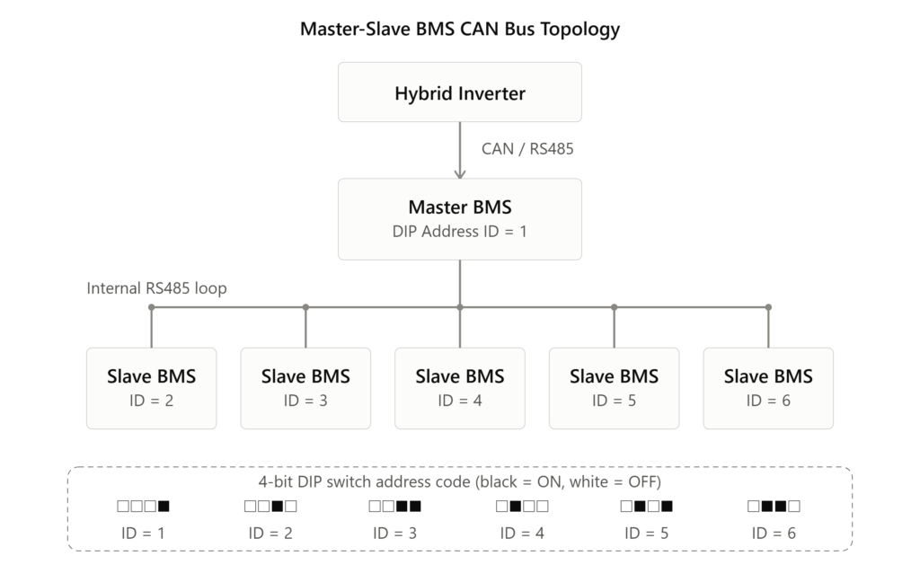
Both the 102Ah and 206Ah platforms run a Master-Slave BMS architecture, paralleling up to 6 identical packs onto a shared DC bus.
Set DIP address ID 1 on the designated Master module. It aggregates bank telemetry and manages closed-loop CAN or RS485 communication with the hybrid inverter.
Assign sequential DIP addresses (ID 2 through 6) to the Slave modules, linking internal telemetry back to the Master via the inter-battery comms link.
System capacity scales linearly across the parallel array:
C_system = N_parallel × E_module
For 102Ah modules (maximum 6 units):
C_system_102Ah = 6 × 5.12 kWh = 30.72 kWh total capacity
For 206Ah modules (maximum 6 units):
C_system_206Ah = 6 × 10.24 kWh = 61.44 kWh total capacity
| Parallel Units | Total Energy (102Ah Module) | Total Energy (206Ah Module) | Combined Continuous Discharge | Recommended Inverter Pairing |
| 1 Unit | 5.12 kWh | 10.24 kWh | 100A / 200A | 1 × 6kW Inverter |
| 2 Units | 10.24 kWh | 20.48 kWh | 200A / 400A | 1 × 6kW or 1 × 12kW Inverter |
| 4 Units | 20.48 kWh | 40.96 kWh | 400A / 800A | 2 × 12kW Parallel Inverters |
| 6 Units (Max) | 30.72 kWh | 61.44 kWh | 600A / 1200A | Multi-Inverter Microgrids |
Field Rule: Match DC cable lengths and gauge exactly between each module terminal and the combiner busbar. Resistance deltas cause uneven current sharing, triggering nuisance BMS overcurrent cutoffs and accelerating cell aging on lower-resistance paths.
5. Application Scenarios & Engineering Selection Matrix
Module selection in off grid solar system sizing hinges on four constraints: daily energy throughput, peak inductive draw, wall load capacity, and expansion scope.
5.1 Selecting the AL-WM512100 (102Ah / 5.12kWh)
- Target Load Profile: 5kWh to 12kWh daily consumption with standard overnight cycling.
- Target Applications: Standard grid-tied residential homes, urban apartments, essential-load backup, and remote telecom sites.
- System Fit: Matches 3kW–6kW hybrid inverters on standard timber/steel stud partitions or projects requiring phased capex investment.
5.2 Selecting the AL-WM512200 (206Ah / 10.24kWh)
- Target Load Profile: >15kWh daily consumption with full-shift autonomy or high baseline night loads.
- Target Applications: Luxury villas, agricultural cold storage, off-grid estates, and light commercial shops.
- System Fit: Pairs with 6kW–12kW hybrid solar inverters supporting high-surge inductive loads (HVAC, submersible well pumps, shop compressors). Requires concrete or structural steel mounting.
5.3 System Sizing Example
- Location: Off-grid Rural Villa
- Daily Consumption: 22kWh/day
- Peak Inverter Load: 9.5kW (HVAC + Submersible Well Pump)
- Autonomy Target: 24 hours (22kWh usable reserve)
Calculation: Total Required Nominal Storage = Daily Consumption / Maximum Usable DoD Total Nominal Storage = 22kWh / 0.80 = 27.5kWh
Hardware Selection: Deploy 3 × AL-WM512200 (206Ah) modules in parallel:
- Nominal Storage: 3 × 10.24kWh = 30.72kWh
- Combined Continuous Discharge: 3 × 200A = 600A bus capacity
The 600A bus easily absorbs the 9.5kW inverter draw (~198A at 48V cutoff). Running at <0.33C preserves cell life and minimizes thermal stress.
6. Installation & Safety Protocols (IEC Compliance)
Safe LiFePO4 deployment demands strict adherence to thermal boundaries and international electrical codes.
6.1 Environmental Operating Boundaries
LiFePO4 chemistry offers excellent thermal stability at high temperatures. However, LiFePO4 low temperature charging below 0°C causes lithium plating on the graphite anode, which permanently reduces capacity.
- Charging Temperature Range: 0°C to 50°C. Below 0°C, the BMS trips low-temp cutoffs to block charge current, while discharge remains fully available.
- Discharging Temperature Range: -15°C to 50°C.
- Enclosure Protection: IP21. Indoor deployment only. Locate units in conditioned utility rooms protected from condensation, falling water droplets, and conductive dust.
+-----------------------------------------------------------------------------------+
| BATTERY OPERATING TEMPERATURE ZONES                                               |
+-----------------------------------------------------------------------------------+
|                                                                                   |
|  -15°C              0°C                                50°C                       |
|   ├─────────────────┼──────────────────────────────────┤                          |
|   │ Discharge Only  │   Full Charge & Discharge Region │                          |
|   └─────────────────┴──────────────────────────────────┘                          |
|                                                                                   |
+-----------------------------------------------------------------------------------+
6.2 Safety Certification Standards
Haven Deer battery modules meet international low-voltage BESS safety and electromagnetic compatibility (EMC) standards:
- Electrical Safety: Integrates with power conversion systems complying with IEC 62109-1, IEC 62109-2, and UL 1741.
- EMC Compliance: Meets EN 61000-6-1, EN 61000-6-3, and FCC Part 15 Class B conducted and radiated emission limits for residential installations.
7. Engineering Summary & Frequently Asked Questions
Battery selection hinges on two hard limits: inverter continuous DC draw and structural wall capacity. For 3kW-6kW inverters, 102Ah modules allow modular scaling on light stud walls. For 12kW platforms, heavy surge loads, or tight plant rooms, 206Ah modules deliver 200A continuous throughput and maximize wall-space density. Before energizing, follow a solar commissioning checklist: verify cable impedance, set Master-Slave DIP addresses, and establish closed-loop BMS comms.
Frequently Asked Questions
Q1: What is the main structural difference when installing 102Ah vs. 206Ah wall-mounted batteries?
The 102Ah pack (45.5kg) allows direct two-person manual mounting on timber/steel studs with rated backing plates or solid masonry. The 206Ah pack (102kg) exceeds safe manual lift limits. It demands mechanical lifting gear and anchor bolting into poured reinforced concrete or structural steel unistrut frames.
Q2: Can I connect 102Ah and 206Ah modules together in the same battery bank?
Never mix capacities in the same bank. Paralleling 102Ah and 206Ah packs creates cell internal resistance (IR) mismatches and uneven current sharing, causing the smaller module to trip overcurrent protection prematurely. Parallel only identical modules.
Q3: How many 102Ah or 206Ah battery modules can be connected in parallel?
The built-in BMS firmware enforces a hard limit of 6 parallel modules per bank. This scales a single DC bus to 30.72kWh (102Ah) or 61.44kWh (206Ah).
Q4: What happens if the ambient temperature drops below 0°C during operation?
The BMS triggers low-temperature charge lockout below 0°C to prevent destructive lithium plating on the anode. Discharge continues uninterrupted down to -15°C.
Q5: Is a single 102Ah battery enough for a 6kW hybrid inverter?
A single 102Ah unit bottlenecks a 6kW inverter. With a 100A continuous limit, battery-only output caps at 4.2kW–5.0kW as voltage sags, requiring active PV generation or grid import to achieve full 6kW inverter rating.
Q6: What communication protocols are used between the battery and the hybrid inverter?
Modules feature CAN, RS485, and RS232 ports to maintain closed-loop telemetry and dynamic charge/discharge current limits (CCL/DCL) with the inverter.
Q7: What is the expected cycle life of Haven Deer wall-mounted batteries?
All modules are rated for ≥6,000 cycles at 90% Depth of Discharge (DoD) and ≥10,000 cycles at 80% DoD under standard testing conditions at 25°C.
Q8: Can these wall-mounted batteries be connected in series to increase system voltage?
Series wiring is strictly prohibited. Stacking modules in series over-voltages the internal BMS circuitry, causes severe arc-flash risks, and voids the product warranty.
Q9: What protection rating do these wall-mounted enclosures carry?
They carry an IP21 protection rating and are rated for indoor installations in clean, weather-protected equipment rooms free from condensation and falling water droplets.
Q10: Can the battery reactivate a hybrid inverter after a deep discharge event?
Yes. An integrated 0V wake-up circuit allows compatible hybrid inverters to jump-start the BMS via PV or grid input, recovering deeply discharged cells without manual external bench chargers.
8. Need Engineering Assistance Sizing Your Off-Grid Battery Bank?
Sizing an off-grid BESS leaves no room for guesswork. Engineering a reliable off-grid solar power system architecture demands direct alignment across PV array generation, inverter surge headroom, continuous DC bus ampacity, and structural wall limits.
Submit your project load profiles to the Haven Deer application engineering team for sizing validation, single-line diagrams (SLDs), and custom OEM/ODM module manufacturing.