Quick Summary: Remote farm microgrids integrate solar PV, LiFePO4 storage, hybrid inverters, and passive dry-contact generator controls. An Energy Management System (EMS) coordinates flows between PV, BESS, grid, and generators. It absorbs inductive motor surges. When battery SoC drops to a configured threshold, the EMS auto-starts the backup generator. It sheds non-essential loads during extended energy deficits.
1. Operational & Electrical Challenges in Remote Agricultural Microgrids
Remote agricultural operations—dairy farms, poultry facilities, and irrigation districts—face chronic power reliability issues. At the end of long rural distribution lines, farms endure voltage sags, phase imbalances, grid instability, and outages that derail daily operations.
Sizing an agricultural BESS requires auditing baseline loads, inductive motor surges, and backup runtimes. Residential solar equipment cannot handle these dynamics.
1.1 Inductive Motor Surges & Heavy Equipment Startup Demand
Inductive motor loads account for most agricultural power consumption. Direct-on-line (DOL) single-phase and three-phase motors power critical farm equipment, including:
- Submersible and centrifugal irrigation pumps
- Milk parlor vacuum pumps and milk chilling compressors
- High-volume ventilation fans and manure handling augers
- Grain drying blowers and automated feed delivery systems
Motors draw locked rotor amps (LRA) during startup. Direct-on-line (DOL) motors pull an instantaneous inrush current 3x to 6x higher than their rated full-load current, aligned with U.S. Department of Energy industrial motor guidelines.
Without sufficient surge capacity or voltage regulation, this inrush triggers inverter overcurrent protection, causing voltage collapse or system trips.
Engineering Tip: Separate resistive loads (like water heaters) from inductive motor loads during site audits. Calculate the largest motor’s LRA on top of the baseline load to determine true peak surge requirements.
1.2 Weak-Grid Instability and Complete Off-Grid Autonomy Requirements
Long feeder lines, weak infrastructure, and unbalanced farm loads cause frequent rural grid voltage fluctuations. Standard grid-tied inverters disconnect when grid voltage or frequency drifts out of limits, killing power despite active solar generation.
| Load Category | Example Equipment | Surge Factor | Sensitivity |
| Inductive Heavy | Irrigation Pumps, Compressors | 3x to 6x | Voltage Sag Critical |
| Inductive Light | Ventilation Fans, Feed Augers | 2x to 3x | Moderate |
| Critical Continuous | Milk Cooling, Cold Storage | 2x to 3x | Temperature Critical |
| Sensitive Electronic | IoT Sensors, Controllers | 1x (None) | Frequency & Waveform |
Farms demand continuous power. Outages jeopardize livestock ventilation, milk refrigeration, and automated feeding. Microgrids solve this by dynamically coordinating solar PV, BESS, grid, and generator inputs.
2. Multi-Input Energy Hub Architecture for Farm Microgrids
An automated farm microgrid cannot rely on solar alone. Weather shifts, seasonal surges, and overnight loads require an integrated Energy Hub to coordinate PV, BESS, grid, and backup generators.
2.1 Coordinating PV, Battery Storage, Grid, and Generator Inputs
Beyond basic DC-to-AC conversion, the low-voltage hybrid inverter houses an Energy Management System (EMS) that routes power between PV, BESS, grid, generator, and farm loads.
- PV Array: Primary generation source running daytime loads and charging the BESS with surplus power.
- LiFePO4 BESS: Bidirectional DC storage that handles overnight loads and absorbs excess daytime PV output.
- Utility Grid (Weak Grid): Auxiliary AC input for backup power, battery top-ups, or emergency operation.
- Backup Generator (Diesel/Gas): Auxiliary AC source auto-triggered via EMS dry contacts during extended outages or low battery SoC.
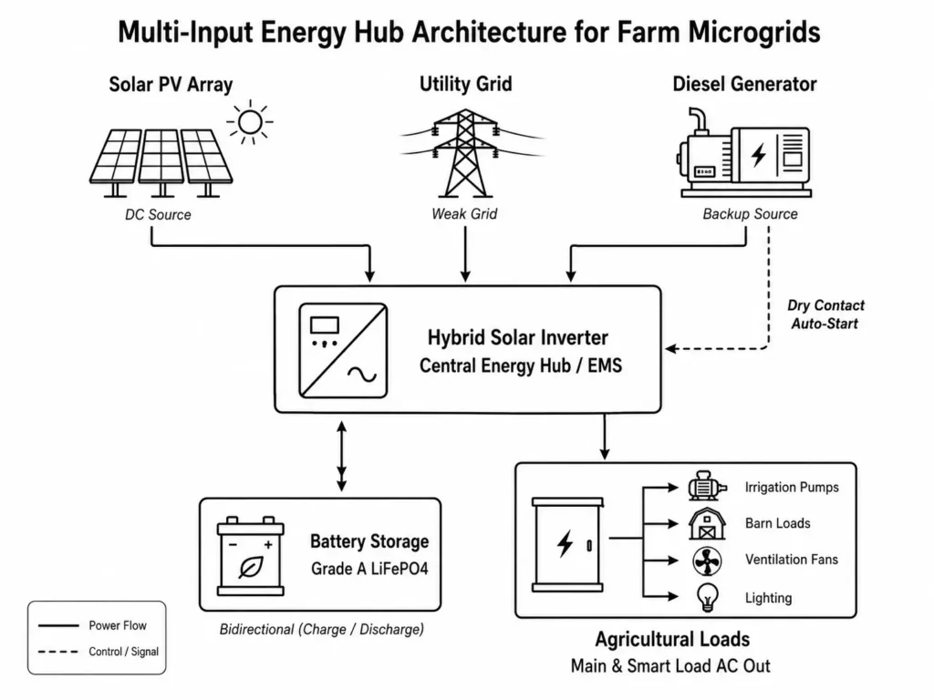
The EMS dynamically manages system operating strategies according to configured energy priority modes and battery protection thresholds:
- SBU Mode (Solar → Battery → Utility): Directs PV to loads and routes excess power to the BESS. When solar drops, the battery discharges down to the low SoC setpoint before handoff to grid or generator power.
- SUB Mode (Solar → Utility → Battery): Runs loads on PV first, supplementing with grid power when solar drops while preserving full battery capacity for grid outages.
2.2 Dual Independent MPPT Optimization for Agricultural Roofs & Fields
Agricultural PV layouts face physical constraints: East-West barn roofs, multi-pitch structures, and shading from silos or grain legs.
When evaluating single MPPT vs. dual MPPT off-grid solar kits for complex farm roofs, dual independent channels—like those on the Haven Deer ALL 4812000 Pro (12kW)—allow separate string configurations across mismatched orientations, tilts, or shading profiles.
| Operational State | Primary Source | Secondary Source | Emergency Backup |
| Daytime / High PV | Solar PV (Supplies Loads) | Battery Charging (Surplus PV) | Grid / Generator OFF |
| Night / Normal | LiFePO4 Battery Discharge | None | Grid Standby |
| Low Battery / Extended Cloudy | Backup Generator (Auto Dry Contact) | Generator AC Battery Charging | Grid (if available) |
Operating independently across a 60–500V DC range, each MPPT on the ALL 4812000 Pro optimizes string output regardless of shading or orientation differences on secondary strings.
Request an Agricultural Microgrid Single-Line Diagram Planning an off-grid or weak-grid farm microgrid? Contact Haven Deer engineering for a custom single-line diagram and topology review.
3. Managing Heavy Inductive Loads & Surge Currents
Direct-on-line motor starting requires precise inverter sizing, surge capacity checks, and parallel engineering for heavy loads.
3.1 Pure Sine Wave Quality & Inverter Peak Surge Ratings (12,000VA–22,000VA)
Inductive motors need clean AC waveforms. Modified sine wave inverters cause harmonic distortion, overheating motor windings, raising noise, and shortening equipment lifespan.
Use pure sine wave inverters to protect inductive motors.
Size inverters for both continuous running wattage and peak motor inrush.
Inverter Surge Requirement = Rated Motor Power × Motor Startup Factor
Where:
- Rated Motor Power = Continuous operating power of the motor in kW or kVA
- Motor Startup Factor = Starting current multiplier, typically 3× to 6× for direct-on-line motors
| Inverter Model | Continuous Output | Peak Surge Output | Max PV Input |
| ALL 486000 Pro | 6,000W / 6kVA | 12,000VA (5 sec) | 9,000W (1 MPPT) |
| ALL 4812000 Pro | 12,000W / 12kVA | 22,000VA (5 sec) | 15,000W (2 MPPT) |
Engineering Example: Irrigation Pump Surge Calculation
Consider a site running a 5.5kW (7.5 HP) DOL centrifugal pump with a 2kW baseline load.
- Running Load: 5.5kW + 2.0kW = 7.5kW total continuous load.
- Startup Surge Calculation: The 5.5kW pump has a 4.5x inrush factor.
- Peak Surge Power Calculation: Peak Surge Power = (5.5 kW × 4.5) + 2.0 kW baseline = 26.75 kW peak demand.
Inverter Selection: A single 6kW unit (12kVA surge) or 12kW unit (22kVA surge) trips under this 26.75kW surge. Paralleling two 12kW inverters delivers 24kW continuous output and 44kVA peak surge, providing ample starting margin.
3.2 Sizing Inverter Arrays in Parallel for High-Tonnage Agricultural Machinery
When site loads exceed single-inverter limits, executing inverter parallel operation for up to 6 units expands continuous output and peak surge capacity across a shared AC bus.
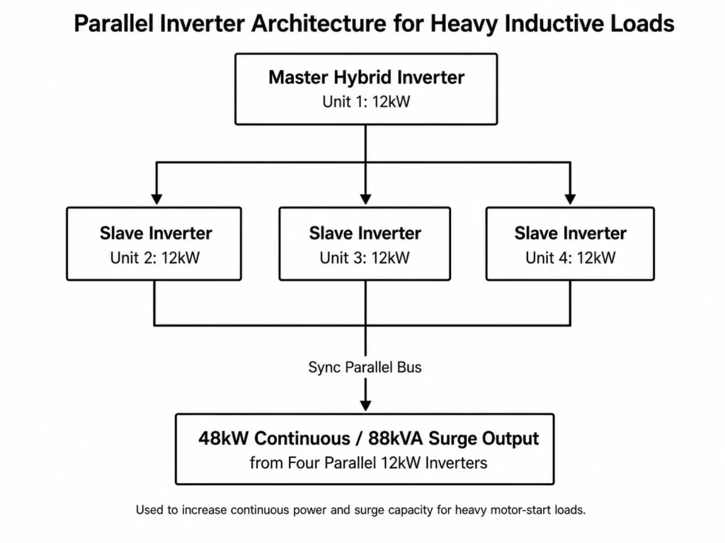
Parallel Installation Field Rules:
- Flash identical firmware and set matching operational parameters across all units.
- Daisy-chain parallel communication cables per manufacturer topology to sync inverter switching.
- Match AC cable lengths and gauge between each inverter and the collection bus to prevent current imbalances.
4. Automated Generator Integration via Passive Dry Contact Relays
Extended cloud cover forces off-grid farms to rely on auxiliary generators. Manual cranking during midnight outages is unworkable. Executing automated generator integration via passive dry contacts automates start and stop cycles based on EMS setpoints.
4.1 Dry Contact Trigger Logic (SoC % vs. Battery Voltage Thresholds)
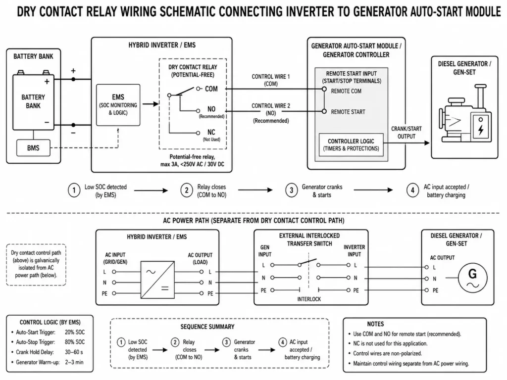
Haven Deer hybrid inverters include a potential-free dry contact relay. Setting dry contact trigger thresholds using SoC % vs. battery voltage allows the EMS to execute automated generator start and stop cycles via the remote-start terminals.
| Control Parameter | Recommended Value | Operational Logic |
| Auto-Start Trigger | 20% SoC (or configured battery voltage threshold) | Relay closes and sends a start signal to generator auto-start controller. |
| Auto-Stop Trigger | 80% SoC (or configured battery voltage threshold) | Relay opens and signals generator controller to begin cool-down and shutdown sequence. |
| Crank Hold Delay | 30 to 60 Seconds | Prevents rapid cycling during temporary load spikes. |
| Generator Warm-up | 2 to 3 Minutes | Allows generator voltage and frequency to stabilize before inverter AC input acceptance. |
The automation sequence functions as follows:
- As loads deplete the BESS, the inverter EMS tracks battery SoC via closed-loop CAN or RS485 communication with the BMS.
- At the low SoC setpoint (e.g., 20%), the EMS closes the dry contact circuit.
- The closed contact signals the generator controller to crank and warm up the engine.
- Once generator AC voltage and frequency stabilize, the inverter accepts input, feeds farm loads, and charges the battery.
- At the high SoC target (e.g., 80%), the EMS opens the relay, triggering the generator cool-down and shutdown cycle.
4.2 AC Input Sharing & Generator Charging Current Limits
Field Warning: Never wire grid power and a generator to the inverter AC input simultaneously. Haven Deer hybrid inverters share a single AC input port; switching between sources requires an external interlocked transfer switch.
When operating on generator power, the total load placed on the generator equals the farm’s active consumption plus the inverter’s battery charging draw:
Total Generator Load = Active Farm Load + Battery Charging Power
Cap the inverter’s Maximum AC Charging Current to match generator limits. For example, with an 8kW continuous diesel generator and a 4kW farm load, limit battery charging power to 4kW to avoid overloading the gen-set.
Generator Auto-Start Pre-Commissioning Verification Checklist
- Verify dry contact wiring polarity and voltage ratings (<250V AC / 30V DC, max 3A).
- Test manual remote-start functionality directly at the generator controller.
- Program low-SoC start and high-SoC stop thresholds in the inverter settings.
- Set Maximum AC Charging Current to match generator continuous output capacity.
- Simulate a low-battery event to test automated cranking, transfer, and shutdown.
5. Dual AC Output Engineering & Smart Load Management
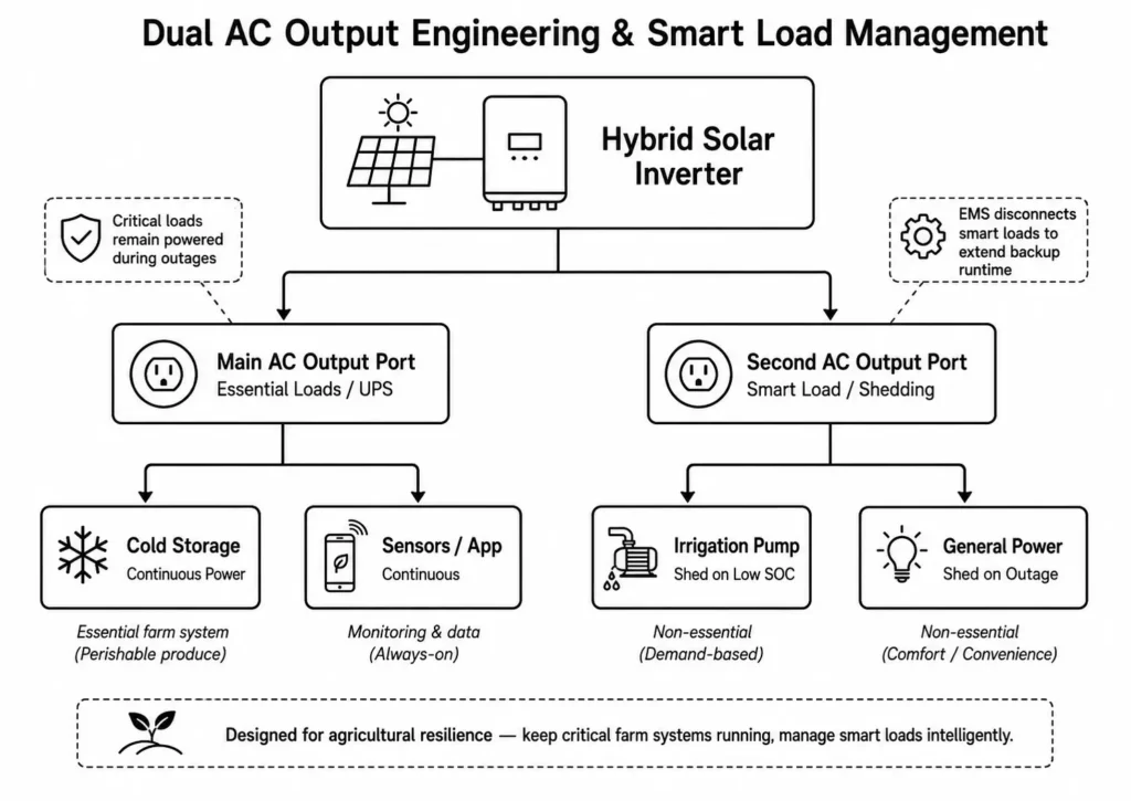
Unchecked loads drain battery capacity during grid outages. Dual AC outputs separate critical loads from non-essential equipment to extend backup runtime.
5.1 Main Output Protection for Essential Farm Systems (Cold Storage, Monitoring)
The hybrid inverter provides two dedicated AC output terminals:
- Main AC Output: Feeds critical infrastructure needing continuous uptime, including cold storage, monitoring, and comms. It delivers UPS-grade transfer speeds: 10ms for sensitive electronics and 20ms for standard loads.
- Second AC Output (Smart Load): Supplies heavy, non-essential equipment that the EMS sheds automatically when battery capacity drops.
| Equipment Category | Connected Output Terminal | Outage Behavior |
| Milk Chilling & Cold Storage | Main AC Output | Uninterrupted |
| Livestock Ventilation Fans | Main AC Output | Uninterrupted |
| Farm Security & IoT Sensors | Main AC Output | Uninterrupted |
| Field Irrigation Pumps | Second AC Output (Smart Load) | Automatically Disconnected |
| Feed Augers & Conveyors | Second AC Output (Smart Load) | Automatically Disconnected |
| General Barn Workshop Outlets | Second AC Output (Smart Load) | Automatically Disconnected |
5.2 Automated Smart Load Shedding for Non-Essential Irrigation Pumps
During outages or low-solar periods, the EMS monitors total load, battery SoC, and reserve power. At the low SoC setpoint, the inverter sheds the Second AC Output to reserve power for core operations.
Shedding high-draw loads like irrigation pumps extends BESS runtime for refrigeration and ventilation without operator intervention.
6. Battery Storage Sizing & Floor-Standing Mobile Cabinet Engineering
Farm BESS installations endure harsh environments, deep daily cycling, and fluctuating motor loads.
6.1 Grade A LiFePO4 Chemistry vs. Traditional Lead-Acid in High-Cycle Farms
Lead-acid banks degrade rapidly on farms due to poor deep-discharge cycle life, cold-weather capacity loss, and heavy maintenance.
Modern farm microgrids rely on Grade A LiFePO4 prismatic cells for superior thermal stability and cycle life.
| Technical Parameter | Haven Deer MB Cabinet LFP | Traditional Deep-Cycle Lead |
| Chemistry | Grade A LiFePO4 Prismatic | Flooded / AGM Lead-Acid |
| Cycle Life @ 90% DoD | ≥ 6,000 Cycles | ~ 300 to 500 Cycles |
| Cycle Life @ 80% DoD | ≥ 10,000 Cycles | ~ 500 to 800 Cycles |
| Usable Depth (DoD) | 80% to 90% Usable Energy | 50% Max Safe Discharge |
| Maintenance Requirement | Minimal Maintenance | Regular Fluid / Terminal Inspection |
| Operating Temperature | -15°C to 50°C (Discharge) | Rapid degradation < 10°C |
| Enclosure Form Factor | Floor-Standing Mobile Cabinet | Open Battery Racks |
LFP delivers exceptional cycle longevity. Haven Deer LFP cabinets achieve ≥6,000 cycles at 90% DoD and 10,000 cycles at 80% DoD, providing a 10+ year operational lifespan.
6.2 Sizing High-Capacity Floor-Standing Batteries (15kWh / 18kWh Modules)
Deploying floor-standing mobile cabinet batteries in 15kWh and 18kWh capacities—such as the Haven Deer MB512300 and MB512346—delivers scalable energy storage for high-demand farm equipment rooms.
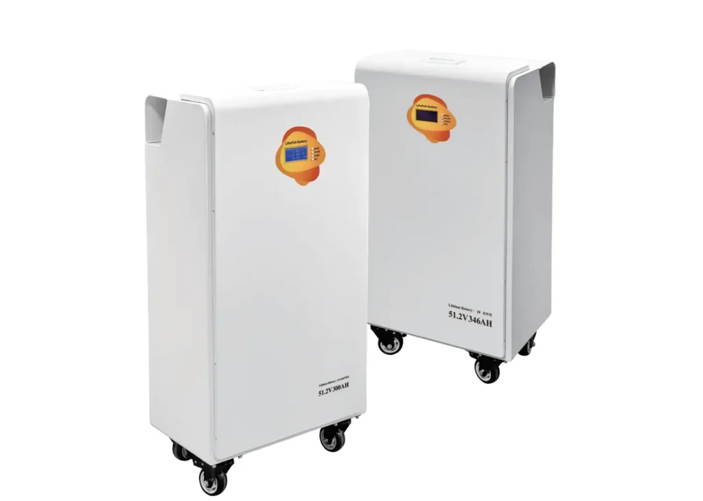
- Heavy-Duty Casters & Foot Levelers: Simplifies positioning and maintenance access in tight equipment rooms.
- Integrated Industrial BMS: Master-Slave architecture supporting CAN and RS485 closed-loop communication with hybrid inverters.
- IP22 Enclosure: Protects against dust and falling water drips in indoor farm environments.
- Modular Parallel Scaling: Parallels up to 6 cabinets on a shared 51.2V DC bus, scaling capacity to 90.0kWh (MB512300) or 108.0kWh (MB512346).
Engineering Tip: Verify floor load-bearing capacity before placement. A single MB512300 weighs 129kg and an MB512346 weighs 163kg. Always install on reinforced concrete pads.
7. Step-by-Step Microgrid Engineering Sizing Calculation
Executing a step-by-step engineering guide to sizing off-grid ESS kits ensures accurate calculations across daily energy loads, peak motor surges, battery autonomy, and PV generation requirements.
7.1 Daily Energy Load Profile & Peak Demand Worksheet
Use these field formulas to size the microgrid:
Step 1: Calculate Total Daily Energy Consumption (kWh/day)
E_daily = Σ(P_i × t_i) / 1000
Where:
- P_i = Operating power of equipment item i in Watts
- t_i = Daily operating time of equipment item i in hours
Step 2: Calculate Required Usable Battery Capacity (kWh)
C_kWh = E_night / (DoD × η_inv)
Where:
- E_night = Energy consumed during non-solar hours in kWh
- DoD = Target Depth of Discharge (0.80 recommended for extended battery cycle life)
- η_inv = Battery-to-AC conversion efficiency of the inverter (0.93 for Haven Deer inverter systems)
Step 3: Calculate Required PV Array Size (kWp)
P_PV = E_daily / (Peak Sun Hours × η_system)
Where:
- Peak Sun Hours = Average daily equivalent solar irradiation hours at the installation location (retrievable via the NREL PVWatts solar resource calculator).
- η_system = Overall efficiency factor (~0.80 accounting for cable resistance, thermal derating, and conversion losses)
7.2 Mathematical Sizing Example for a 20-Hectare Dairy Farm
Site Load Audit Data:
- Milk Chilling System: 3.5kW load operating 6 hours/day (21 kWh/day) — Main Output
- Ventilation Fans: 2.0kW load operating 12 hours/day (24 kWh/day) — Main Output
- Barn Lighting & Monitoring: 1.0kW load operating 14 hours/day (14 kWh/day) — Main Output
- Irrigation Pump: 5.5kW load (direct-on-line) operating 4 hours/day (22 kWh/day) — Smart Load
- Total Daily Energy Consumption: 21 + 24 + 14 + 22 = 81 kWh/day
- Night Energy Consumption (Main Output): 25 kWh (non-solar hours)
- Local Solar Irradiation: 4.5 Peak Sun Hours/day
Step-by-Step System Sizing Execution:
- Inverter Selection:
- Total continuous load demand = 3.5 + 2.0 + 1.0 + 5.5 = 12.0 kW.
- The 5.5kW pump demands 24.75 kVA peak inrush (5.5 kW × 4.5 multiplier).
- Selection: Two Haven Deer ALL 4812000 Pro (12kW) units in parallel = 24kW continuous / 44kVA peak surge.
- Battery Bank Sizing:
- Night consumption = 25 kWh.
- Required Battery Capacity = 25 kWh / (0.80 × 0.93) = 33.6 kWh.
- Selection: Three Haven Deer MB512300 Floor-Standing Mobile Cabinet Batteries (3 × 15.0 kWh = 45.0 kWh total storage).
- PV Array Sizing:
- Required PV Peak Capacity = 81 kWh / (4.5 Peak Sun Hours × 0.80) = 22.5 kWp.
- Selection: Thirty-six (36) 610W Monocrystalline PV Modules (21.96 kWp total). Configure modules into four strings of nine, splitting them evenly across the Dual MPPT inputs of both parallel inverters.
- Generator Auto-Start Backup:
- One 15kVA Auto-Start Diesel Generator wired to the passive dry contact relay of Inverter 1.
| Component Description | Specification / Model | Quantity Selected |
| Hybrid Solar Inverter | ALL 4812000 Pro (12kW) | 2 Units (Parallel = 24kW) |
| Battery Storage Cabinet | MB512300 (15.0kWh) | 3 Cabinets (45.0kWh Total) |
| High-Efficiency Solar PV | 610W Mono Grade A | 36 Panels (21.96kWp Total) |
| DC Array Protection | IP65 PV Combiner Box | 1 Unit (DC SPD and 32A String Protection Fuse) |
| Automated Generator | 15kVA Diesel Generator | 1 Unit (Dry Contact Auto-Start) |
8. System Commissioning, Protection & IEC Compliance Standards
Field-ready agricultural microgrids require strict compliance, clean installation, and disciplined commissioning.
8.1 Safety & EMC Standards (IEC 62109-1/2, IP21/IP22 Enclosures)
Hardware deployed in farm microgrids must meet core electrical and safety standards:
- Safety Compliance: Hybrid inverters must meet the IEC 62109-1 safety requirements for power conversion equipment. Lithium BESS cabinets must comply with the IEC 62619 industrial lithium battery safety standard.
- Electromagnetic Compatibility (EMC): Compliance with EN 61000 prevents inverter switching noise from interfering with farm IoT sensors, telemetry, and automated controls.
- Enclosure Protection: Indoor hybrid inverters use IP21 and floor-standing battery cabinets use IP22. Outdoor combiner boxes require IP65 enclosures to resist dust and washdowns.
8.2 Pre-Commissioning Checklist for Agricultural Field Engineers
Complete this checklist before energizing the microgrid:
- DC Open-Circuit Voltage Check: Measure Voc on every string. Calculate temperature coefficients to ensure cold-weather Voc stays below the 500V DC MPPT limit.
- Polarity & Grounding Audit: Verify DC polarity at combiner boxes, battery terminals, and inverter inputs. Bond solar racking, inverter chassis, and battery cabinets to a common earth ground.
- BMS Communication Handshake: Connect CAN/RS485 cables between Master BMS and inverter. Set DIP switches, power up the BESS, and verify active closed-loop communication on the inverter display.
- Dry Contact Relay Test: Manually trip the dry contact output via inverter menu settings to confirm remote-start signaling to the generator controller.
- Parallel AC Balance: Match AC conductor gauge and cable length from each parallel inverter to the distribution bus to ensure equal current sharing.
- Smart Load Shedding Test: Cut grid input to trigger battery mode, then verify the Second AC Output sheds non-essential loads at the configured low SoC setpoint.
9. Frequently Asked Questions
How does an automated microgrid handle high starting currents from large irrigation pumps?
Hybrid inverters absorb motor inrush via high surge capacity. The Haven Deer ALL 4812000 Pro delivers a 22,000VA peak surge for 5 seconds. If larger DOL pump motors exceed single-inverter capacity, parallel up to 6 units on a shared AC bus.
What signal triggers the diesel generator to automatically start?
The inverter EMS tracks battery SoC via closed-loop BMS communication. At a low SoC setpoint (e.g., 20%), the inverter closes its passive dry contact relay. This signals the generator controller to crank and warm up the engine.
Can the backup generator charge the batteries and power farm loads at the same time?
Yes. Connected to the inverter AC input, the generator powers farm loads while the internal charger tops up the BESS within configured current limits.
What is the purpose of Dual AC Output in farm microgrids?
Dual AC output separates critical systems (milk chilling, ventilation, sensors) from non-essential equipment (irrigation pumps). During outages, the EMS sheds the Second AC Output to extend BESS runtime for core operations.
Why is Grade A LiFePO4 chemistry preferred over lead-acid for agricultural storage?
Grade A LiFePO4 prismatic cells deliver ≥6,000 cycles at 90% DoD and 10,000 cycles at 80% DoD. LFP provides high thermal stability, deeper usable energy, and zero routine maintenance compared to lead-acid banks.
Can utility grid power and generator power be connected to the hybrid inverter simultaneously?
No. Grid power and generator output share a single AC input port. Connecting both simultaneously requires an external interlocked transfer switch or ATS.
How does cold weather affect LiFePO4 battery charging on remote farms?
Haven Deer BMS blocks charging below 0°C to prevent lithium plating. Discharging operates down to -15°C or -20°C. Sub-zero environments require thermal insulation or cabinet heaters.
Is a PV combiner box required for agricultural solar microgrids?
Yes. Multi-string arrays require an IP65 PV combiner box with string fuses and DC surge arrestors to isolate strings and block overvoltage spikes.
How many battery cabinets can be connected in parallel for large farm systems?
Parallel up to 6 floor-standing cabinets (MB512300 or MB512346) on a shared 51.2V DC bus. This scales capacity up to 90.0kWh or 108.0kWh.
What communication protocol connects the inverter EMS to the battery BMS?
The inverter and BMS communicate in closed-loop via industrial CAN or RS485 protocols. This exchanges SoC, cell temperature, current limits, and status flags for dynamic EMS control.
What transfer speed occurs when grid power fails on a farm?
Haven Deer hybrid inverters switch in 10ms for UPS critical loads and 20ms for general equipment, preventing controller resets during grid outages.
What warranty and expected service life do Haven Deer farm battery cabinets carry?
Haven Deer Grade A LiFePO4 cabinets include a 5-year factory warranty and deliver a 10+ year service life under daily deep cycling.
10. Request an Agricultural Microgrid Engineering Review
Designing or commissioning an off-grid microgrid for a farm, dairy, or irrigation project?
Haven Deer supplies pre-engineered off-grid solar ESS kits pairing high-capacity hybrid inverters, Grade A LiFePO4 battery cabinets, and IP65 combiner boxes built for harsh farm environments.
Contact Haven Deer engineering for a custom microgrid sizing review and single-line diagram.